Computer Organization and Architecture – Processor Design
Overview of CPU Design
The operation or task that must perform by CPU are:
Fetch Instruction: The CPU reads an instruction from memory.
Interpret Instruction: The instruction is decoded to determine what action is required.
Fetch Data: The execution of an instruction may require reading data from memory or I/O module.
Process data: The execution of an instruction may require performing some arithmetic or logical operation on data.
Write data: The result of an execution may require writing data to memory or an I/O module.
To do these tasks, it should be clear that the CPU needs to store some data temporarily. It must remember the location of the last instruction so that it can know where to get the next instruction. It needs to store instructions and data temporarily while an instruction is begin executed. In other words, the CPU needs a small internal memory. These storage location are generally referred as registers.
The major components of the CPU are an arithmetic and logic unit (ALU) and a control unit (CU). The ALU does the actual computation or processing of data. The CU controls the movement of data and instruction into and out of the CPU and controls the operation of the ALU.
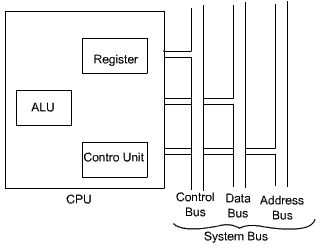
The CPU is connected to the rest of the system through system bus. Through system bus, data or information gets transferred between the CPU and the other component of the system. The system bus may have three components:
Data Bus:
Data bus is used to transfer the data between main memory and CPU.
Address Bus:
Address bus is used to access a particular memory location by putting the address of the memory location.
Control Bus:
Control bus is used to provide the different control signal generated by CPU to different part of the system. As for example, memory read is a signal generated by CPU to indicate that a memory read operation has to be performed. Through control bus this signal is transferred to memory module to indicate the required operation.
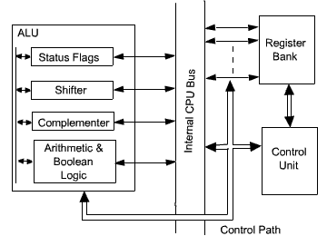
There are three basic components of CPU: register bank, ALU and Control Unit. There are several data movements between these units and for that an internal CPU bus is used. Internal CPU bus is needed to transfer data between the various registers and the ALU.
The internal organization of CPU in more abstract level is shown in the Figure below

Figure : CPU with the system Bus

Figure : Internal Structure of the CPU
Register Organization
A computer system employs a memory hierarchy. At the highest level of hierarchy, memory is faster, smaller and more expensive. Within the CPU, there is a set of registers which can be treated as a memory in the highest level of hierarchy. The registers in the CPU can be categorized into two groups:
User-visible registers: These enables the machine – or assembly-language programmer to minimize main memory reference by optimizing use of registers.
Control and status registers: These are used by the control unit to control the operation of the CPU. Operating system programs may also use these in privileged mode to control the execution of program.
User-visible Registers:
The user-visible registars can be categorized as follows:
General Purpose Registers
Data Registers
Address Registers
Condition Codes
General-purpose registers can be assigned to a variety of functions by the programmer. In some cases, general- purpose registers can be used for addressing functions (e.g., register indirect, displacement).
In other cases, there is a partial or clean separation between data registers and address registers.
Data registers may be used to hold only data and cannot be employed in the calculation of an operand address.
Address registers may be somewhat general purpose, or they may be devoted to a particular addressing mode. Examples include the following:
Segment pointer: In a machine with segment addressing, a segment register holds the address of the base of the segment. There may be multiple registers, one for the code segment and one for the data segment.
Index registers: These are used for indexed addressing and may be auto indexed.
Stack pointer: If there is user visible stack addressing, then typically the stack is in memory and there is a dedicated register that points to the top of the stack.
Condition Codes (also referred to as flags) are bits set by the CPU hardware as the result of the operations. For example, an arithmetic operation may produce a positive, negative, zero or overflow result. In addition to the result itself begin stored in a register or memory, a condition code is also set. The code may be subsequently be tested as part of a condition branch operation. Condition code bits are collected into one or more registers.
Register Organization
There are a variety of CPU registers that are employed to control the operation of the CPU. Most of these, on most machines, are not visible to the user.
Different machines will have different register organizations and use different terminology. We will discuss here the most commonly used registers which are part of most of the machines.
Four registers are essential to instruction execution:
Program Counter (PC): Contains the address of an instruction to be fetched. Typically, the PC is updated by the CPU after each instruction fetched so that it always points to the next instruction to be executed. A branch or skip instruction will also modify the contents of the PC.
Instruction Register (IR): Contains the instruction most recently fetched. The fetched instruction is loaded into an IR, where the opcode and operand specifiers are analyzed.
Memory Address Register (MAR): Contains the address of a location of main memory from where information has to be fetched or information has to be stored. Contents of MAR is directly connected to the address bus.
Memory Buffer Register (MBR): Contains a word of data to be written to memory or the word most recently read. Contents of MBR is directly connected to the data bus.It is also known as Memory Data Register(MDR).
Apart from these specific register, we may have some temporary registers which are not visible to the user. As such, there may be temporary buffering registers at the boundary to the ALU; these registers serve as input and output registers for the ALU and exchange data with the MBR and user visible registers.
Processor Status Word
All CPU designs include a register or set of registers, often known as the processor status word (PSW), that contains status information.
The PSW typically contains condition codes plus other status information. Common fields or flags include the following:
Sign: Contains the sign bit of the result of the last arithmetic operation.
Zero: Set when the result is zero.
Carry: Set if an operation resulted in a carry (addition) into or borrow (subtraction) out of a high order bit.
Equal: Set if a logical compare result is equal.
Overflow: Used to indicate arithmetic overflow.
Interrupt enable/disable: Used to enable or disable interrupts.
Supervisor: Indicate whether the CPU is executing in supervisor or user mode.
Certain privileged instructions can be executed only in supervisor mode, and certain areas of memory can be accessed only in supervisor mode.
Apart from these, a number of other registers related to status and control might be found in a particular CPU design. In addition to the PSW, there may be a pointer to a block of memory containing additional status information (e.g. process control blocks).