Computer Organization and Architecture – I/O system organisation
Input/Output Organization
The computer system’s input/output (I/O) architecture is its interface to the outside world.
Till now we have discussed the two important modules of the computer system – The processor and The memory module.
The third key component of a computer system is a set of I/O modules
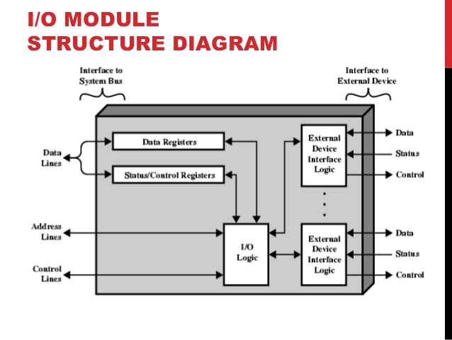
Each I/O module interfaces to the system bus and controls one or more peripheral devices.
There are several reasons why an I/O device or peripheral device is not directly connected to the system bus. Some of them are as follows –
There are a wide variety of peripherals with various methods of operation. It would be impractical to include the necessary logic within the processor to control several devices.
The data transfer rate of peripherals is often much slower than that of the memory or processor. Thus, it is impractical to use the high-speed system bus to communicate directly with a peripheral.
Peripherals often use different data formats and word lengths than the computer to which they are attached.Thus, an I/O module is required.
Input/Output Modules
The major functions of an I/O module are categorized as follows –
- Control and timing
- Processor Communication
- Device Communication
- Data Buffering
- Error Detection
During any period of time, the processor may communicate with one or more external devices in unpredictable manner, depending on the program’s need for I/O.
The internal resources, such as main memory and the system bus, must be shared among a number of activities, including data I/O.
Control & timings:
The I/O function includes a control and timing requirement to co-ordinate the flow of traffic between internal resources and external devices.
For example, the control of the transfer of data from an external device to the processor might involve the following sequence of steps –
- The processor interacts with the I/O module to check the status of the attached device.
- The I/O module returns the device status.
- If the device is operational and ready to transmit, the processor requests the transfer of data, by means of a command to the I/O module.
- The I/O module obtains a unit of data from external device.
- The data are transferred from the I/O module to the processor.
- If the system employs a bus, then each of the interactions between the processor and the I/O module involves one or more bus arbitration’s.
Processor & Device Communication
During the I/O operation, the I/O module must communicate with the processor and with the external device.
Processor communication involves the following –
Command decoding :
The I/O module accepts command from the processor, typically sent as signals on control bus.
Data :
Data are exchanged between the processor and the I/O module over the data bus.
Status Reporting :
Because peripherals are so slow, it is important to know the status of the I/O module. For example, if an I/O module is asked to send data to the processor(read), it may not be ready to do so because it is still working on the previous I/O command. This fact can be reported with a status signal. Common status signals are BUSY and READY.
Address Recognition :
Just as each word of memory has an address, so thus each of the I/O devices. Thus an I/O module must recognize one unique address for each peripheral it controls.
On the other hand, the I/O must be able to perform device communication. This communication involves command, status information and data.
Data Buffering:
An essential task of an I/O module is data buffering. The data buffering is required due to the mismatch of the speed of CPU, memory and other peripheral devices. In general, the speed of CPU is higher than the speed of the other peripheral devices. So, the I/O modules store the data in a data buffer and regulate the transfer of data as per the speed of the devices.
In the opposite direction, data are buffered so as not to tie up the memory in a slow transfer operation. Thus the I/O module must be able to operate at both device and memory speed.
Error Detection:
Another task of I/O module is error detection and for subsequently reporting error to the processor. One class or error includes mechanical and electrical malfunctions reported by the device (e.g. paper jam). Another class consists of unintentional changes to the bit pattern as it is transmitted from devices to the I/O module.
There will be many I/O devices connected through I/O modules to the system. Each device will be identified by a unique address.
When the processor issues an I/O command, the command contains the address of the device that is used by the command. The I/O module must interpret the addres lines to check if the command is for itself.
Generally in most of the processors, the processor, main memory and I/O share a common bus(data address and control bus).
Two types of addressing are possible –
- Memory-mapped I/O
- Isolated or I/O mapped I/O
Memory-mapped I/O:
There is a single address space for memory locations and I/O devices.
The processor treats the status and address register of the I/O modules as memory location.
For example, if the size of address bus of a processor is 16, then there are 216 combinations and all together 216 address locations can be addressed with these 16 address lines.
Out of these 216 address locations, some address locations can be used to address I/O devices and other locations are used to address memory locations.
Since I/O devices are included in the same memory address space, so the status and address registers of I/O modules are treated as memory location by the processor. Therefore, the same machine instructions are used to access both memory and I/O devices.
Isolated or I/O -mapped I/O:
In this scheme, the full range of addresses may be available for both.
The address refers to a memory location or an I/O device is specified with the help of a command line.
In general command line is used to identify a memory location or an I/O device.
if =1, it indicates that the address present in address bus is the address of an I/O device.
if =0, it indicates that the address present in address bus is the address of a memory location.
Since full range of address is available for both memory and I/O devices, so, with 16 address lines, the system may now support both 2 16 memory locations and 2 16 I/O addresses.