Data Communication and Networking – Networking Components study Notes
Introduction
HILI subcommittee (IEEE802.1) of the IEEE identified the following possible internetworking scenarios.
- A single LAN
- Two LANs connected together (LAN-LAN)
- A LAN connected to a WAN (LAN-WAN)
- Two LANs connected through a WAN (LAN-WAN-LAN) Various internetworking devices such as hubs, bridges, switches, routers and gateways are required to link them together.
RJ-45
RJ-45 , short form of Registered Jack – 45 , is an eight wired connector that is used to connect computers on a
local area network(LAN), especially Ethernet. RJ-45 connectors look similar to the RJ-11 connector used for
connecting telephone equipment, but they are somewhat wider
Ethernet Card
An Ethernet card is a kind of network adapter and is also known as Network Interface Card (NIC). These
adapters support the Ethernet standard for high-speed network connections via cables. An Ethernet Card
contains connections for either coaxial or twisted pair cables or even for fibre optic cable.
These internetworking devices are introduced in this lesson.
various internetworking devices:
- Repeaters
- Hubs
- Bridges
- Switches
- Routers
- Gateways
Repeaters
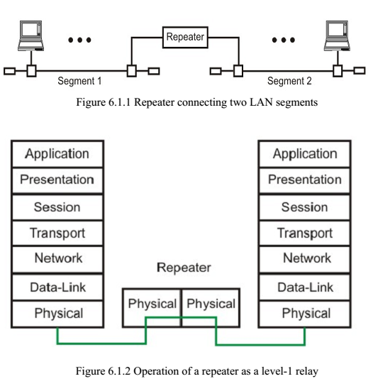
A single Ethernet segment can have a maximum length of 500 meters with a maximum of 100 stations (in a cheapernet segment it is 185m). To extend the length of the network, a repeater may be used as shown in Fig. 6.1.1. Functionally, a repeater can be considered as two transceivers joined together and connected to two different segments of coaxial cable. The repeater passes the digital signal bit-by-bit in both directions between the two segments. As the signal passes through a repeater, it is amplified and regenerated at the other end. The repeater does not isolate one segment from the other, if there is a collision on one segment, it is regenerated on the other segment. Therefore, the two segments form a single LAN and it is transparent to rest of the system. Ethernet allows five segments to be used in cascade to have a maximum network span of 2.5 km. With reference of the ISO model, a repeater is considered as a level-1 relay as depicted in Fig. 6.1.2. It simply repeats, retimes and amplifies the bits it receives.
The repeater is merely used to extend the span of a single LAN. Important features of a repeater are as follows:
- A repeater connects different segments of a LAN
- A repeater forwards every frame it receives
- A repeater is a regenerator, not an amplifier
- It can be used to create a single extended LAN
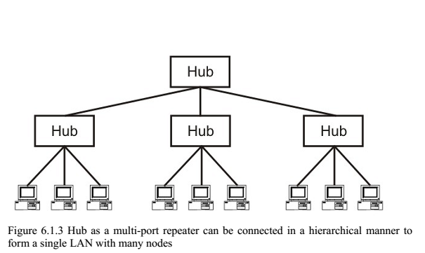
Hubs
Hub is a generic term, but commonly refers to a multiport repeater. It can be used to create multiple levels of hierarchy of stations. The stations connect to the hub with RJ-45 connector having maximum segment length is 100 meters. This type of interconnected set of stations is easy to maintain and diagnose. Figure 6.1.3 shows how several hubs can be connected in a hierarchical manner to realize a single LAN of bigger size with a large number of nodes.
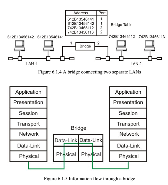
Bridges
The device that can be used to interconnect two separate LANs is known as a bridge. It is commonly used to connect two similar or dissimilar LANs as shown in Fig. 6.1.4. The bridge operates in layer 2, that is data-link layer and that is why it is called level-2 relay with reference to the OSI model. It links similar or dissimilar LANs, designed to store and forward frames, it is protocol independent and transparent to the end stations. The flow of information through a bridge is shown in Fig. 6.1.5. Use of bridges offer a number of advantages, such as higher reliability, performance, security, convenience and larger geographic coverage. But, it is desirable that the quality of service (QOS) offered by a bridge should match that of a single LAN. The parameters that define the QOS include availability, frame mishaps, transit delay, frame lifetime, undetected bit errors,
frame size and priority.
Key features of a bridge are mentioned below:
- A bridge operates both in physical and data-link layer
- A bridge uses a table for filtering/routing
- A bridge does not change the physical (MAC) addresses in a frame
- Types of bridges:
Transparent Bridges
Source routing bridges
A bridge must contain addressing and routing capability. Two routing algorithms have been proposed for a bridged LAN environment. The first, produced as an extension of IEEE 802.1 and applicable to all IEEE 802 LANs, is known as transparent bridge. And the other, developed for the IEEE 802.5 token rings, is based on source routing
approach. It applies to many types of LAN including token ring, token bus and CSMA/CD bus.
Transparent Bridges
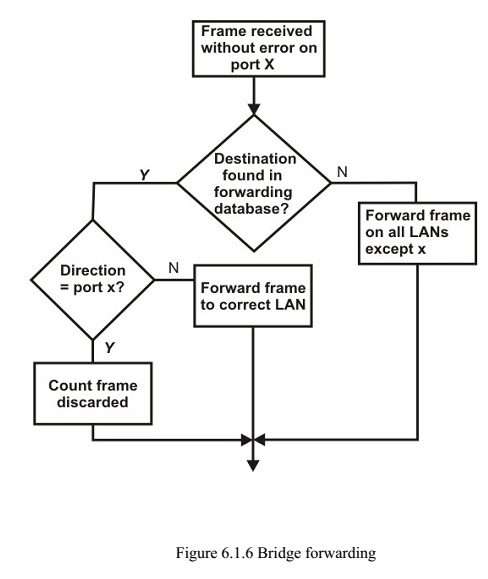
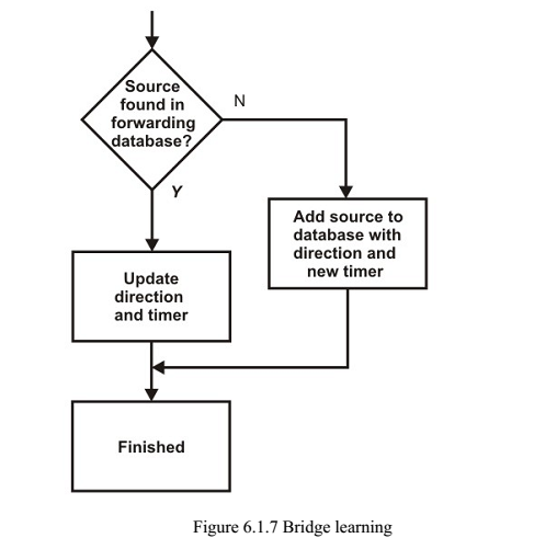
The transparent bridge uses two processes known as bridge forwarding and bridge learning.
If the destination address is present in the forwarding database already created, the packet is forwarded to the port number to which the destination host is attached. If it is not present, forwarding is done on all parts (flooding). This process is known as bridge forwarding. Moreover, as each frame arrives, its source address indicates where a particular host is situated, so that the bridge learns which way to forward frames to that address.This process is known as bridge learning.
Key features of a transparent bridge are:
- The stations are unaware of the presence of a transparent bridge
- Reconfiguration of the bridge is not necessary; it can be added/removed without being noticed
- It performs two functions:
- Forwarding of frames
- Learning to create the forwarding table
1 Bridge Forwarding
Bridge forwarding operation is expla functions of the bridge forwarding are
- Discard the frame if source and destination addresses are same
- Forward the frame if the source and destinatio destination address is present in the table
- Use flooding if destination address is not present in the table
2 Bridge Learning
Source Routing Bridges
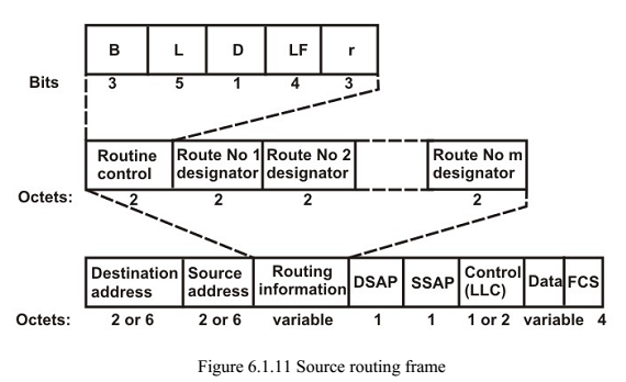
The second approach, known as source routing, where the routing operation is performed by the source host and the frame specifies which route the frame is to follow. A host can discover a route by sending a discovery frame, which spreads through the entire network using all possible paths to the destination. Each frame gradually gathers addresses as it goes. The destination responds to each frame and the source host chooses an appropriate route from these responses. For example, a route with minimum hop-count can be chosen. Whereas transparent bridges do not modify a frame, a source routing bridge adds a routing information field to the frame. Source routing approach provides a shortest path at the cost of the proliferation of discovery frames, which can put a serious extra burden on the network. Figure 6.1.11 shows the frame format of a source routing bridge.
Switches
A switch is essentially a fast bridge having additional sophistication that allows faster processing of frames.
Some of important functionalities are:
- Ports are provided with buffer
- Switch maintains a directory: #address – port#
- Each frame is forwarded after examining the #address and forwarded to the proper port#
- Three possible forwarding approaches: Cut-through, Collision-free and Fullybuffered as briefly explained below.
Cut-through: A switch forwards a frame immediately after receiving the destination address. As a consequence, the switch forwards the frame without collision and error detection.
Collision-free: In this case, the switch forwards the frame after receiving 64 bytes, which allows detection of collision. However, error detection is not possible because switch is yet to receive the entire frame.
Fully buffered: In this case, the switch forwards the frame only after receiving the entire frame. So, the switch can detect both collision and error free frames are forwarded.
Comparison between a switch and a hub
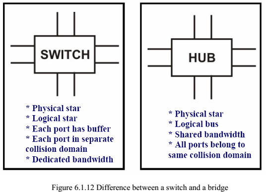
Although a hub and a switch apparently look similar, they have significant differences. As shown in Fig. 6.1.12, both can be used to realize physical star topology, the hubs works like a logical bus, because the same signal is repeated on all the ports. On the other hand, a switch functions like a logical star with the possibility of the communication of separate signals between any pair of port lines. As a consequence, all the ports of a hub belong to the same collision domain, and in case of a switch each port operates on separate collision domain. Moreover, in case of a hub, the bandwidth is shared by all the stations connected to all the ports. On the other hand, in case of a switch, each port has dedicated bandwidth. Therefore, switches can be used to increase the bandwidth of a hubbased network by replacing the hubs by switches.
Routers
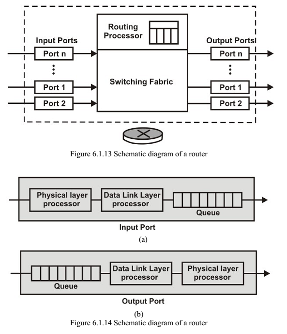
A router is considered as a layer-3 relay that operates in the network layer, that is it acts on network layer frames. It can be used to link two dissimilar LANs. A router isolates LANs in to subnets to manage and control network traffic. However, unlike bridges it is not transparent to end stations. A schematic diagram of the router is shown on Fig. 6.1.13. A router has four basic components: Input ports, output ports, the routing processor and the switching fabric. The functions of the four components are briefly mentioned below.
- Input port performs physical and data-link layer functions of the router. As shown in Fig. 6.1.14 (a), the ports are also provided with buffer to hold the packet before forwarding to the switching fabric.
- Output ports, as shown in Fig. 6.1.14(b), perform the same functions as the input ports, but in the reverse order.
- The routing processor performs the function of the network layer. The process involves table lookup.
- The switching fabric, shown in Fig. 6.1.15, moves the packet from the input queue to the output queue by using specialized mechanisms. The switching fabric is realized with the help of multistage interconnection networks.
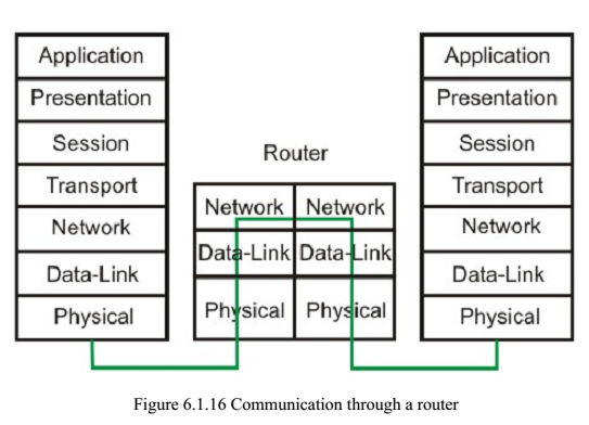
- Communication of a frame through a router is shown in Fig. 6.1.16.
Gateways
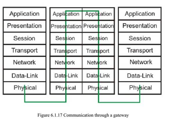
A gateway works above the network layer, such as application layer as shown in Fig. 6.1.17. As a consequence, it is known as a Layer-7 relay. The application level gateways can look into the content application layer packets such as email before forwarding it to the other side. This property has made it suitable for use in Firewalls
A Simple Internet
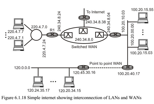
A simple internet comprising several LANs and WANs linked with the help of routers is shown in Fig. 6.1.18.
Buy Book – Data-Communications-Networking-Behrouz-Forouzan