Data Communication and Networking – Communication Protocols- X.25 Study Notes
Introduction
In the early 1970’s there were many data communication networks (also known as Public Networks), which were owned by private companies, organizations and governments agencies. Since those public networks were quite different internally, and the interconnection of networks was growing very fast, there was a need for a common network interface protocol. In 1976 X.25 was recommended as the desired protocol by the International Consultative Committee for Telegraphy and Telephony (CCITT) called the International Telecommunication Union (ITU) since 1993.
X.25 is a standard for WAN communications that defines how connections between user devices and network devices are established and maintained. X.25 is designed to operate effectively regardless of the type of systems connected to the network. It is typically used in the packet-switched networks (PSNs) of common carriers, such as the telephone companies. Subscribers are charged based on their use of the network.
X.25 Devices and Protocol Operation
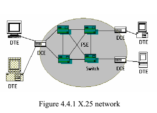
X.25 network devices fall into three general categories: data terminal equipment (DTE), data circuit-terminating equipment (DCE), and packet-switching exchange (PSE) as shown in Fig. 4.4.1.
Data terminal equipment (DTE)
Data terminal equipment (DTE) devices are end systems that communicate across the X.25 network. They are usually terminals, personal computers, or network hosts, and are located on the premises of individual subscribers. Data communication Equipments (DCEs) are communications devices, such as modems and packet switches that provide the interface between DTE devices and a PSE, and are generally located in the carrier’s facilities.
PSEs
PSEs are switches that compose the bulk of the carrier’s network. They transfer data from one DTE device to another through the X.25 PSN. Figure 4.4.1 illustrates the relationships among the three types of X.25 network devices
Packet Assembler/Disassembler
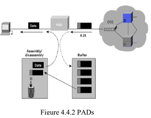
The packet assembler/disassembler (PAD) is a device commonly found in X.25 networks. PADs are used when a DTE device, such as a character-mode terminal, is too simple to implement the full X.25 functionality. The PAD is located between a DTE device and a DCE device, and it performs three primary functions: buffering (storing data until a device is ready to process it), packet assembly, and packet disassembly. The PAD buffers data sent to or from the DTE device. It also assembles outgoing data into packets and forwards them to the DCE device. (This includes adding an X.25 header.) Finally, the PAD disassembles incoming packets before forwarding the data to the DTE. (This includes removing the X.25 header) Figure 4.4.2 illustrates the basic operation of the PAD when receiving packets from the X.25 WAN.
X.25 session establishment and virtual circuits
Session Establishment X.25
Session Establishment X.25 sessions are established when one DTE device contacts another to request a communication session. It’s up to the receiving DTE whether to accept or refuse the connection. If the request is accepted, the two systems begin full-duplex communication. Either DTE device can terminate the connection. After the session is terminated, any further communication requires the establishment of a new session.
Virtual Circuits The X.25
Virtual Circuits The X.25 is a packet-switched virtual circuit network. A virtual circuit is a logical connection created to ensure reliable communication between two network devices. A virtual circuit denotes the existence of a logical, bidirectional path from one DTE device to another across an X.25 network. Physically, the connection can pass through any number of intermediate nodes, such as DCE devices and PSEs. Virtual circuits in X.25 are created at the network layer such that multiple virtual circuits (logical connections) can be multiplexed onto a single physical circuit (a physical connection). Virtual circuits are demultiplexed at the remote end, and data is sent to the appropriate destinations.
Figure 4.4.3 illustrates separate virtual circuits being multiplexed onto a single physical circuit.
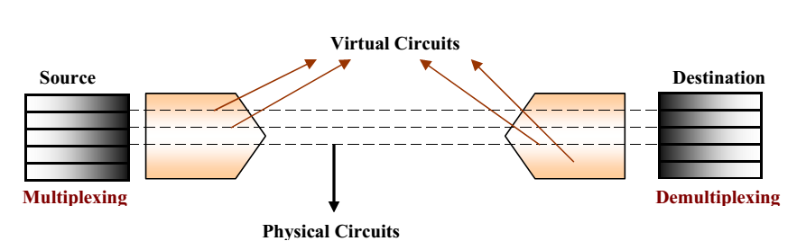
Figure 4.4.3 Physical Circuits and Virtual Circuit
Two types of X.25 virtual circuits exist: switched and permanent. Switched virtual
circuits (SVCs) are temporary connections used for sporadic data transfers. They require that two DTE devices to establish, maintain, and terminate a session each time the devices need to communicate. Permanent virtual circuits (PVCs) are permanently established connections used for frequent and consistent data transfers. PVCs do not require that sessions be established and terminated.
Therefore, DTEs can begin transferring data whenever necessary because the session is always active. The basic operation of an X.25 virtual circuit begins when the source DTE device specifies the virtual circuit to be used (in the packet headers) and then sends the packets to a locally connected DCE device. At this point, the local DCE device examines the packet headers to determine which virtual circuit to use and then sends the packets to the closest PSE in the path of that virtual circuit. PSEs (switches) pass the traffic to the next intermediate node in the path, which may be another switch or the remote DCE device. When the traffic arrives at the remote DCE device, the packet headers are examined and the destination address is determined. The packets are then sent to the destination DTE device. If communication occurs over an SVC and neither device has additional data to transfer, the virtual circuit is terminated.
X.25 Protocol Suite
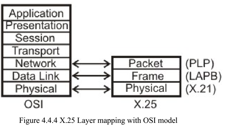
The X.25 protocol suite maps to the lowest three layers of the OSI reference model as shown in Figure 4.4.4. The layers are:
- Physical layer: Deals with the physical interface between an attached station and the link that attaches that station to the packet-switching node. o X.21 is the most commonly used physical layer standard.
- Frame layer: Facilitates reliable transfer of data across the physical link by transmitting the data as a sequence of frames. Uses a subset of HDLC known as Link Access Protocol Balanced (LAPB), bit oriented protocol.
- Packet layer: Responsible for end-to-end connection between two DTEs. Functions performed are: o Establishing connection o Transferring data o Terminating a connection o Error and flow control o With the help of X.25 packet layer, data are transmitted in packets over external virtual circuits.
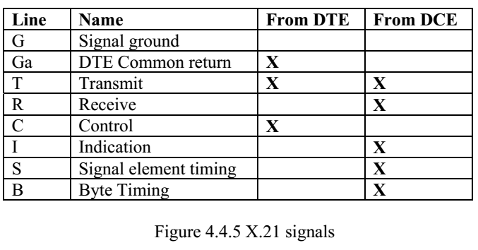
Physical Layer At the physical layer X.21 is specifically defined for X.25 by ITU-T. The X.21 interface operates over eight interchange circuits (i.e., signal ground, DTE common return, transmit, receive, control, indication, signal element timing and byte timing) their functions is defined in recommendation of X.24 and their electrical characteristics in recommendation of X.27. The recommendation specifies how the DTE can setup and clear calls by exchanging signals with the DCE.
The physical connector has 15 pins, but not all of them are used. The DTE uses the T and C circuits to transmit data and control information. The DCE uses the R and I circuits for data and control. The S circuit contains a signal stream emitted by the DCE to provide timing information so the DTE knows when each bit interval starts and stops. The B circuit may also provide to group the bits into byte frames. If this option is not provided the DCE and DTE must begin every control sequence with at least two SYN characters to enable each other to deduce the implied frame boundary.
- Link Layer The link layer (also called level 2, or frame level) ensures reliable transfer of data between the DTE and the DCE, by transmitting the data as a sequence of frames (a frame is an individual data unit which contains address, control, information field etc.).
The functions performed by the link level include:
- Transfer of data in an efficient and timely fashion.
- Synchronization of the link to ensure that the receiver is in step with the transmitter.
- Detection of transmission errors and recovery from such errors
- Identification and reporting of procedural errors to higher levels, for recovery.
The link level uses data link control procedures, which are compatible with the High Level Data Link (HDLC) standardized by ISO, and with the Advanced Data Communications Control Procedures (ADCCP) standardized by the U.S. American National Standards Institute (ANSI).
There are several protocols, which can be used in the link level:
- Link Access Protocol, Balanced (LAPB) is derived from HDLC and is the most commonly used. It enables to form a logical link connection besides all the other characteristics of HDLC.
- Link Access Protocol (LAP) is an earlier version of LAPB and is seldom used today.
- Link Access Procedure, D Channel (LAPD) is derived from LAPB and it is used for Integrated Services Digital Networks (ISDN) i.e. it enables data transmission between DTEs through D channel, especially between a DTE and an ISDN node.
- Logical Link Control (LLC) is an IEEE 802 Local Area Network (LAN) protocol, which enables X.25 packets to be transmitted through a LAN channel.
Now let us discuss the most commonly used link layer protocol, i.e. LAPB. LAPB is a bit-oriented protocol that ensures that frames are correctly ordered and error-free. There are three kinds of frames:
1. Information: This kind of frame contains the actual information being transferred and some control information. The control field in these frames contains the frame sequence number. I-frame functions include sequencing, flow control, and error detection and recovery. I-frames carry send- and receive-sequence numbers.
2. Supervisory: The supervisory frame (S-frame) carries control information. Sframe functions include requesting and suspending transmissions, reporting on status, and acknowledging the receipt of I-frames. S-frames carry only receivesequence numbers.
There are various types of supervisory frames.
- RECEIVE READY-Acknowledgment frame indicating the next frame expected.
- REJECT-Negative acknowledgment frame used to indicate transmission error detection.
- RECEIVE NOT READY (RNR)-Just as RECEIVE READY but tells the sender to stop sending due to temporary problems.
3. Unnumbered: This kind of frames is used only for control purposes. U-frame functions include link setup and disconnection, as well as error reporting. U frames carry no sequence numbers.
Packet Level
This level governs the end-to-end communications between the different DTE devices. Layer 3 is concerned with connection set-up and teardown and flow control between the DTE devices, as well as network routing functions and the multiplexing of simultaneous logical connections over a single physical connection. PLP is the network layer protocol of X.25.
Call setup mode is used to establish SVCs between DTE devices. A PLP uses the X.121 addressing scheme to set up the virtual circuit. The call setup mode is executed on a pervirtual-circuit basis, which means that one virtual circuit can be in call setup mode while another is in data transfer mode. This mode is used only with SVCs, not with PVCs. To establish a connection on an SVC, the calling DTE sends a Call Request Packet, which includes the address of the remote DTE to be contacted. The destination DTE decides whether or not to accept the call (the Call Request packet includes the sender’s DTE address, as well as other information that the called DTE can use to decide whether or not to accept the call). A call is accepted by issuing a Call Accepted packet, or cleared by
issuing a Clear Request packet. Once the originating DTE receives the Call Accepted packet, the virtual circuit is established and data transfer may take place.
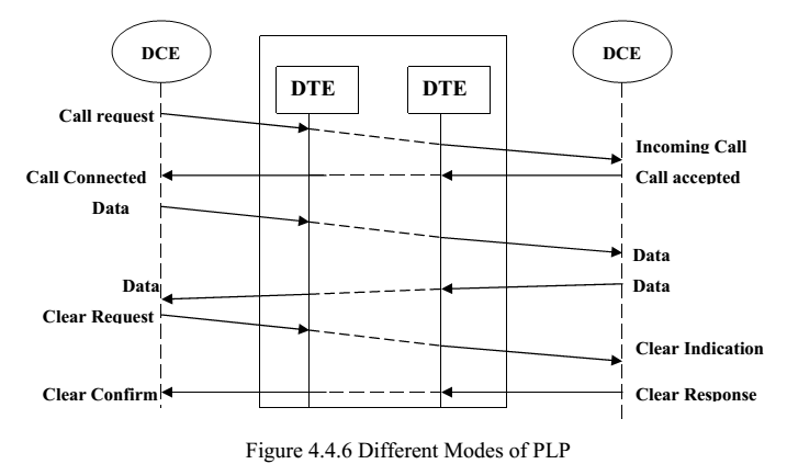
Different phases of call set-up, data transfer, call release has been shown in Fig. 4.4.6. The PLP operates in five distinct modes: call setup, data transfer, idle, call clearing, and restarting.
- Data transfer mode is used for transferring data between two DTE devices across a virtual circuit. In this mode, PLP handles segmentation and reassembly, bit padding, and error and flow control. This mode is executed on a per-virtual-circuit basis and is used with both PVCs and SVCs.
- Idle mode is used when a virtual circuit is established but data transfer is not occurring. It is executed on a per-virtual-circuit basis and is used only with SVCs.
- Call clearing mode is used to end communication sessions between DTE devices and to terminate SVCs. This mode is executed on a per-virtual-circuit basis and is used only with SVCs. When either DTE wishes to terminate the call, a Clear Request packet is sent to the remote DTE, which responds with a Clear Confirmation packet.
- Restarting mode is used to synchronize transmission between a DTE device and a locally connected DCE device. This mode is not executed on a per-virtualcircuit basis. It affects all the DTE device’s established virtual circuits.
Four types of PLP packet fields exist:
- General Format Identifier (GFI)—Identifies packet parameters, such as whether the packet carries user data or control information, what kind of windowing is being used, and whether delivery confirmation is required.
- Logical Channel Identifier (LCI)—identifies the virtual circuit across the local DTE/DCE interface.
- Packet Type Identifier (PTI)—identifies the packet as one of 17 different PLP packet types.
- User Data—Contains encapsulated upper-layer information. This field is present only in data packets. Otherwise, additional fields containing control information are added.
Buy Book – Data-Communications-Networking-Behrouz-Forouzan