Data Communication and Networking – OSI Model Study Notes
OPEN SYSTEMS INTER CONNECTION REFERENCE MODEL (OSIRM )
Introduction to OSI Model & its layers
- The Open Systems Interconnection (OSI) Model was developed by International Organization for Standardization (ISO).
- ISO is the organization, OSI is the model
- It was developed to allow systems with different platforms to communicate with each other. Platform could mean hardware, software or operating system.
- It is a network model that defines the protocols for network communications.
- It is a hierarchical model that groups its processes into layers.
- It has 7 layers as follows: (Top to Bottom)
- Application Layer
- Presentation Layer
- Session Layer
- Transport Layer
- Network Layer
- Data Link Layer
- Physical Layer
Each layer has specific duties to perform and has to cooperate with the layers above and below it.
Layered Architecture of OSI Model
- The OSI model has 7 layers each with its own dedicated task.
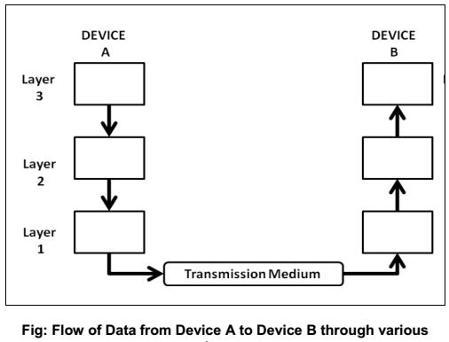
- A message sent from Device A to Device B passes has to pass through all layers at A from top to bottom then all layers at B from bottom to top as shown in the figure below.
- At Device A, the message is sent from the top layer i.e Application Layer A then all the layers till it reaches its
physical layer and then it is transmitted through the transmission medium. - At Device B, the message received by the physical layer passes through all its other layers and moves upwards till it reaches its Application Layer.
- As the message travels from device A to device B, it may pass through many intermediate nodes. These intermediate nodes usually involve only the first three layers of the OSI model as shown below.
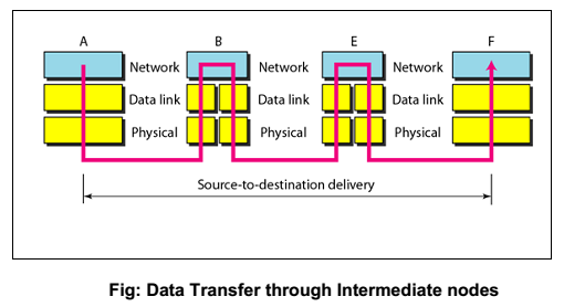
- The Data Link layer determines the next node where the message is supposed to be forwarded and the network layer determines the final recipient.
Communication & Interfaces
- For communication to occur, each layer in the sending device adds its own information to the message it receives from the layer just above it and passes the whole package to the layer just below it. Each layer in the receiving device removes the information added at the corresponding layer and sends the obtained data to the layer above it.
- Every Layer has its own dedicated function or services and is different from the function of the other layers.
- On every sending device, each layer calls upon the service offered by the layer below it.
- On every receiving device, each layer calls upon the service offered by the layer above it.
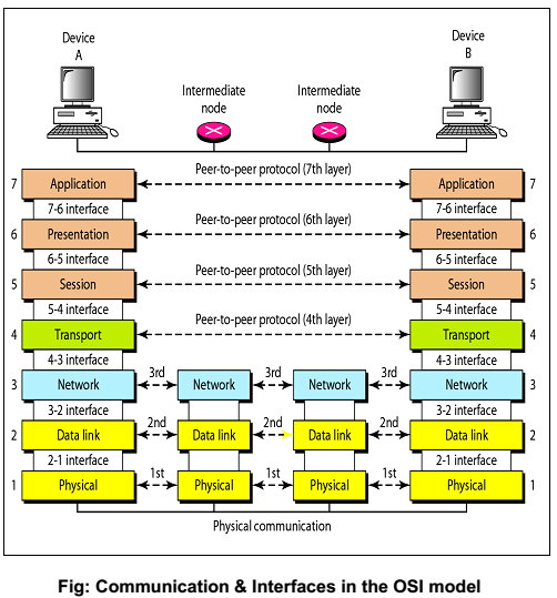
- Between two devices, the layers at corresponding levels communicate with each other .i.e layer 2 at receiving end can communicate and understand data from layer 2 of sending end. This is called peer –to – peer communication.
- For this communication to be possible between every two adjacent layers there is an interface. An interface defines the service that a layer must provide. Every layer has an interface to the layer above and below it as shown in the figure below
Encapsulation of Data
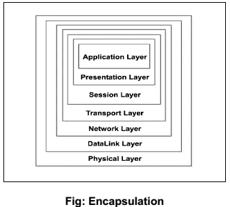
- As shown in the figure above the data at layer 7 i.e the Application layer along with the header added at layer 7 is given to layer 6, the Presentation layer.
- This layer adds Its header and passed the whole package to the layer below.
- The corresponding layers at the receiving side removes the corresponding header added at that layer and sends the remaining data to the above layer.
- The above process is called encapsulation
Description of Layers in the OSI Model
1 Physical Layer
I. The Physical Layer provides a standardized interface to physical transmission media, including :
a. Mechanical specification of electrical connectors and cables, for example maximum cable length
b. Electrical specification of transmission line
c. Bit-by-bit or symbol-by-symbol delivery
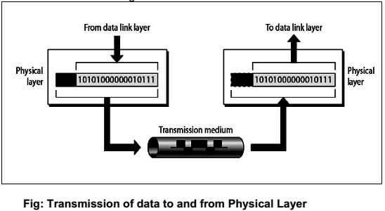
II. On the sender side, the physical layer receives the data from Data Link Layer and encodes it into signals to be transmitted onto the medium. On the receiver side, the physical layer receives the signals from the transmission medium decodes it back into data and sends it to the Data Link Layer as shown in the figure below:
III. Interface
The Physical Layer defines the characteristics of interfaces between the devices & transmission medium.
IV. Representation of bits
The physical layer is concerned with transmission of signals from one device to another which involves converting data (1‘s & 0‘s) into signals and vice versa. It is not concerned with the meaning or interpretation of bits.
V. Data rate
The physical layer defines the data transmission rate i.e. number of bits sent per second. It is the responsibility of the
physical layer to maintain the defined data rate.
VI. Synchronization of bits
To interpret correct and accurate data the sender and receiver have to maintain the same bit rate and also have
synchronized clocks.
VII. Line configuration
The physical layer defines the nature of the connection .i.e. a point to point link, or a multi point link.
VIII. Physical Topology
The physical layer defines the type of topology in which the device is connected to the network. In a mesh topology it
uses a multipoint connection and other topologies it uses a point to point connection to send data.
IX. Transmission mode
The physical layer defines the direction of data transfer between the sender and receiver. Two devices can transfer
the data in simplex, half duplex or full duplex mode
X. Main responsibility of the physical layer
Transmission of bits from one hop to the next.
2 Data Link Layer
I. The Data Link layer adds reliability to the physical layer by providing error detection and correction mechanisms.
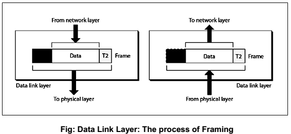
II. On the sender side, the Data Link layer receives the data from Network Layer and divides the stream of bits intofixed size manageable units called as Frames and sends it to the physical layer. On the receiver side, the data link layer receives the stream of bits from the physical layer and regroups them into frames and sends them to the Network layer. This process is called Framing. It is shown in the figure below:
III. Physical Addressing (inside / outside senders network)
a. The Data link layer appends the physical address in the header of the frame before sending it to physical layer.
b. The physical address contains the address of the sender and receiver.
c. In case the receiver happens to be on the same physical network as the sender; the receiver is at only one hop from the sender and the receiver address contains the receiver‘s physical address.
d. In case the receiver is not directly connected to the sender, the physical address is the address of the next node where the data is supposed to be delivered.
IV. Flow control
a. The data link layer makes sure that the sender sends the data at a speed at which the receiver can receive it else if there is an overflow at the receiver side the data will be lost.
b. The data link layer imposes flow control mechanism over the sender and receiver to avoid overwhelming of the receiver.
V. Error control
a. The data link layer imposes error control mechanism to identify lost or damaged frames, duplicate frames and then retransmit them.
b. Error control information is present in the trailer of a frame.
VI. Access Control
a. The data link layer imposes access control mechanism to determine which device has right to send data in an multipoint connection scenario.
VII. Main Responsibility
i. The main responsibility of the data link layer is hop to hop transmission of frames.
3 Network Layer
I. The network layer makes sure that the data is delivered to the receiver despite multiple intermediate devices.
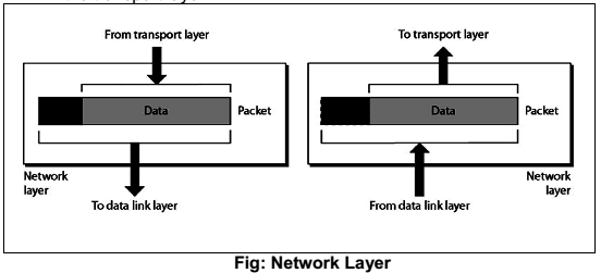
II. The network layer at the sending side accepts data from the transport layer, divides it into packets, adds addressing information in the header and passes it to the data link layer.At the receiving end the network layer receives the frames sent by data link layer, converts them back into packets, verifies the physical address (verifies if the receiver address matches with its own address) and the send the packets to the transport layer.
III. The network layer is responsible for source to destination of delivery of data. Hence it may have to route the data through multiple networks via multiple intermediate devices. In order to achieve this the network layer relies on two things:
a. Logical Addressing
b. Routing
IV. Logical Addressing
The network layer uses logical address commonly known as IP address to recognize devices on the network. An IP address is a universally unique address which enables the network layer to identify devices outside the sender‘s network.
The header appended by the network layer contains the actual sender and receiver IP address. At every hop the network layer of the intermediate node check the IP address in the header, if its own IP address does not match with the IP address of the receiver found in the header, the intermediate node concludes that it is not the final node but an intermediate node and passes the packet to the data link layer where the data is forwarded to the next node.
V. Routing
VI. The network layer divides data into units called packets of equal size and bears a sequence number for rearranging on the receiving end. Each packet is independent of the other and may travel using different routes to reach the receiver hence may arrive out of turn at the receiver. Hence every intermediate node which encounters a packet tries to compute the best possible path for the packet.
The best possible path may depend on several factors such as congestion, number of hops, etc This process of finding the best path is called as Routing. It is done using routing algorithms.
VI. The Network layer does not perform any flow control or error control
VII. Main Responsibility
The main responsibility of Network Layer is transmission of packets from source to destination
4 Transport Layer
I. A logical address at network layer facilitates the transmission of data from source to destination device. But the source and the destination both may be having multiple processes communicating with each other.Hence it is important to deliver the data not only from the sender to the receiver but from the correct process on the sender to the correct process on the receiver.The transport layer takes care of process to process delivery of data and makes sure that it is intact and in order.
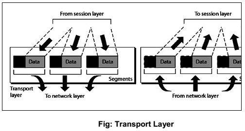
II. At the sending side, the transport layer receives data from the session layer, divides it into units called
segments and sends it to the network layer. At the receiving side, the transport layer receives packets from the network layer, converts and arranges into proper sequence of segments and sends it to the session layer.
III. To ensure process to process delivery the transport layer makes use of port address to identify the data from the sending and receiving process. A Port Address is the name or label given to a process. It is a
16 bit address. Ex. TELNET uses port address 23, HTTP uses port address 80. Port address is also
called as Service Point Address
IV. The data can be transported in a connection oriented or connectionless manner. If the connection is
connection oriented then all segments are received in order else they are independent of each other and are received out of order and have to be rearranged.
V. The Transport layer is responsible for segmentation and reassembly of the message into segments which bear sequence numbers. This numbering enables the receiving transport layer to rearrange the segments in proper order.
VI. Flow Control & Error control: the transport layer also carries out flow control and error control functions; but unlike data link layer these are end to end rather than node to node.
VII. Main Responsibility
The main responsibility of the transport layer is process to process delivery of the entire message.
5 Session Layer
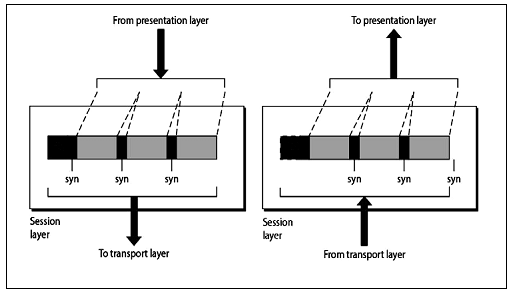
I. The session layer establishes a session between the communicating devices called dialog and synchronizes their interaction. It is the responsibility of the session layer to establish and synchronize the dialogs. It is also called the network dialog controller.
II. The session layer at the sending side accepts data from the presentation layer adds checkpoints to it called syn bits and passes the data to the transport layer. At the receiving end the session layer receives data from the transport layer removes the checkpoints inserted previously and passes the data to the presentation layer.
III. The checkpoints or synchronization points is a way of informing the status of the data transfer. Ex. A checkpoint after first 500 bits of data will ensure that those 500 bits are not sent again in case of retransmission at 650th bit.
IV. Main responsibility of session layer is dialog control and synchronization
6 Presentation Layer
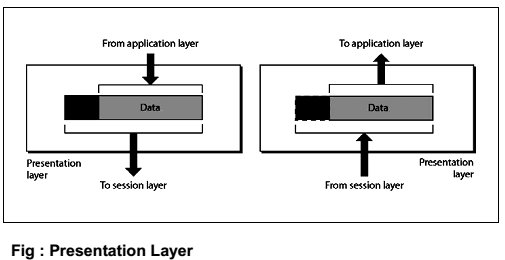
I. The communicating devices may be having different platforms. The presentation layer performs translation, encryption and compression of data
II. The presentation layer at sending side receives the data from the application layer adds header which contains information related to encryption and compression and sends it to the session layer. At the receiving side, the presentation layer receives data from the session layer decompresses and decrypts the data as required and translates it back as per the encoding scheme used at the receiver.
III. Translation
The sending and receiving devices may run on different platforms (hardware, software and operating system). Hence it is important that they understand the messages that are used for communicating. Hence a translation service may be required which is provided by the Presentation layers
IV. Compression
Compression ensures faster data transfer. The data compressed at sender has to be decompressed at the receiving end, both performed by the Presentation layer.
V. Encryption
It is the process of transforming the original message to change its meaning before sending it. The reverse process called decryption has to be performed at the receiving end to recover the original message from the encrypted message.
VI. Main responsibility
The main responsibility of the Presentation layer is translation, compression and encryption.
7.Application Layer
I. The application layer enables the user to communicate its data to the receiver by providing certain services. For ex. Email is sent using X.400 service.
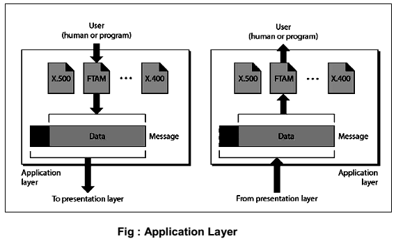
II. X500 is a directory service used to provide information and access to distributed objects
III. X400 is services that provides basis for mail storage and forwarding
IV. FTAM (File transfer, access and management) provides access to files stored on remote computers
and mechanism for transfer and manage them locally.
V. Main Responsibility
Main Responsibility of Application layer is to provide access to network resources.
Buy Book – Data-Communications-Networking-Behrouz-Forouzan