Digital Electronics – Multiplexers and De-multiplexers
Multiplexers
A multiplexer or MUX, also called a data selector, is a combinational circuit with more than one input line, one output line and more than one selection line. There are some multiplexer ICs that provide complementary outputs. Also, multiplexers in IC form almost invariably have an ENABLE or STROBE input, which needs to be active for the multiplexer to be able to perform its intended function.
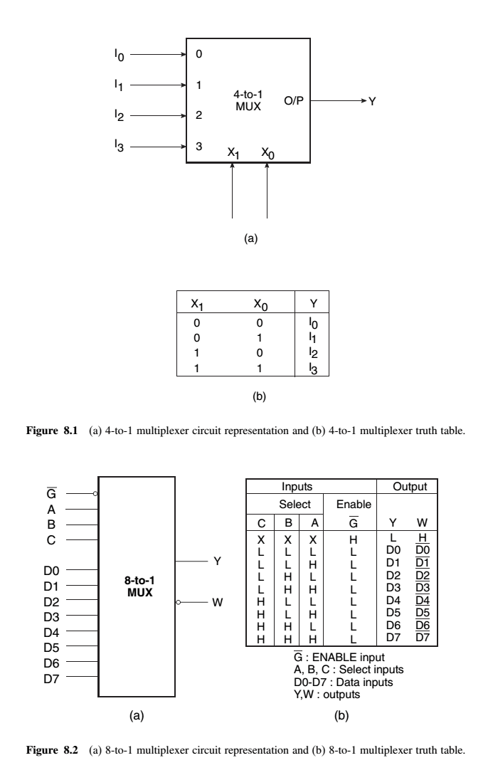
A multiplexer selects binary information present on any one of the input lines, depending upon the logic status of the selection inputs, and routes it to the output line. If there are n selection lines, then the number of maximum possible input lines is 2n and the multiplexer is referred to as a 2^n-to-1 multiplexer or 2^n ×1 multiplexer. Figures below (a) and (b) respectively show the circuit representation and truth table of a basic 4-to-1 multiplexer.
multiplexers usually have an ENABLE input that can be used to control the multiplexing function. When this input is enabled, that is, when it is in logic ‘1’ or logic ‘0’ state, depending upon whether the ENABLE input is active HIGH or active LOW respectively, the output is enabled. The multiplexer functions normally.
When the ENABLE input is inactive, the output is disabled and permanently goes to either logic ‘0’ or logic ‘1’ state, depending upon whether the output is uncomplemented or complemented.
Multiplexers for Parallel-to-Serial Data Conversion
Although data are processed in parallel in many digital systems to achieve faster processing speeds, when it comes to transmitting these data relatively large distances, this is done serially. The parallel arrangement in this case is highly undesirable as it would require a large number of transmission lines. Multiplexers can possibly be used for parallel-to-serial conversion
Cascading Multiplexer Circuits
There can possibly be a situation where the desired number of input channels is not available in IC multiplexers. A multiple number of devices of a given size can be used to construct multiplexers that can handle a larger number of input channels. For instance, 8-to-1 multiplexers can be used to construct 16-to-1 or 32-to-1 or even larger multiplexer circuits.
The basic steps to be followed to carry out the design are as follows:
- 1. If 2^n is the number of input lines in the available multiplexer and 2^N is the number of input lines in the desired multiplexer, then the number of individual multiplexers required to construct the desired multiplexer circuit would be 2^(N−n).
- 2. From the knowledge of the number of selection inputs of the available multiplexer and that of the
desired multiplexer, connect the less significant bits of the selection inputs of the desired multiplexer
to the selection inputs of the available multiplexer. - 3. The left-over bits of the selection inputs of the desired multiplexer circuit are used to enable or
disable the individual multiplexers so that their outputs when ORed produce the final output.
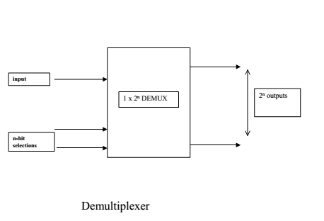
Demultiplexers
A demultiplexer is a combinational logic circuit with an input line, 2^n output lines and n select lines. It routes the information present on the input line to any of the output lines. The output line that gets the information present on the input line is decided by the bit status of the selection lines. Figure below (a) shows the circuit representation of a 1-to-4 demultiplexer. Figure below (b) shows the truth table of the demultiplexer when the input line is held HIGH.

- A demultiplexer basically reverses the multiplexing function. It takes data from one line and distributes them to given number of output lines.
- A demultiplexer has N = 2k output lines, k address selection and one data line. The number of the output line active is specified by the k bits address