Digital Electronics – Decoders-Encoders
Decoders and encoders are fundamental digital circuits used in digital electronics. They are designed to convert between different representations of data, such as binary codes, addresses, or signals. Let’s explore decoders and encoders in more detail:
1.Decoders:
As its name indicates, a decoder is a circuit component that decodes an input code. Given a binary code of n-bits, a decoder will tell which code is this out of the 2^n possible codes
Thus, a decoder has n-inputs and 2^n outputs. Each of the 2^n outputs corresponds to one of the possible 2^n input combinations.
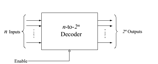
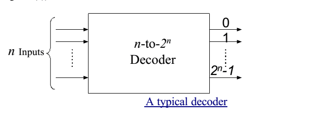
Figure shows the block diagram of a typical decoder, which has n input lines, and m output lines, where m is equal to 2^n . The decoder is called n-to-m decoder. Apart from this, there is also a single line connected to the decoder called enable line. The operations of the enable line will be discussed in the flowing text.
- In general, output i equals 1 if and only if the input binary code has a value of i.
- Thus, each output line equals 1 at only one input combination but is equal to 0 at all other combinations.
- In other words, each decoder output corresponds to a minterm of the n input variables.
- Thus, the decoder generates all of the 2^n minterms of n input variables.
Example: 2-to-4 decoders
Let us discuss the operation and combinational circuit design of a decoder by taking the specific example of a 2-to-4 decoder. It contains two inputs denoted by A1 and A0 and four outputs denoted by D0, D1, D2, and D3 as shown in figure 2. Also note that A1 is the MSB while A0 is the LSB.
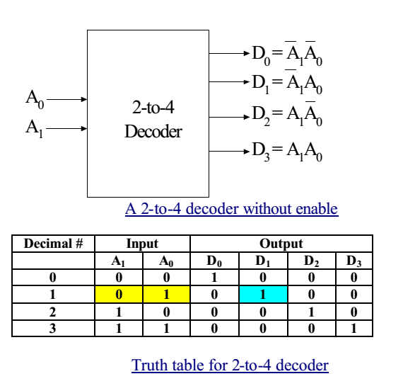
As we see in the truth table (table 1), for each input combination, one output line is activated, that is, the output line corresponding to the input combination becomes 1, while other lines remain inactive. For example, an input of 00 at the input will activate line D0. 01 at the input will activate line D1, and so on.
The “enable” input in decoders
Generally, decoders have the “enable” input .The enable input perroms no logical operation, but is only responsible for making the decoder ACTIVE or INACTIVE. o If the enable “E” o is zero, then all outputs are zero regardless of the input values. o is one, then the decoder performs its normal operation.
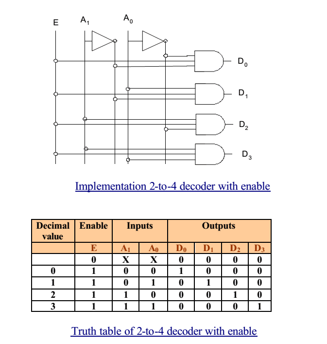
For example, consider the 2-to-4 decoder with the enable input (Figure 4). The enable input is only responsible for making the decoder active or inactive. If Enable E is zero, then all outputs of the decoder will be zeros, regardless of the values of A1 and A0. However, if E is 1, then the decoder will perform its normal operation, as is shown in the
truth table (table 2). In this table we see that as long as E is zero, the outputs D0 to D3 will remain zero, no matter whatever value you provide at the inputs A1 A0, depicted by two don’t cares. When E becomes 1, then we see the same behavior as we saw in the case of 2-to-4 decoder discussed earlier.
Decoder Expansion
- It is possible to build larger decoders using two or more smaller ones.
- For example, a 6-to-64 decoder can be designed with four 4-to-16 decoders and one 2-to-4 line decoder.
2. Encoders:
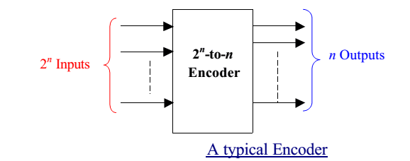
- An encoder performs the inverse operation of a decoder, as shown in Figure 10.
- It has 2^n inputs, and n output lines.
- Only one input can be logic 1 at any given time (active input). All other inputs must be 0’s.
- Output lines generate the binary code corresponding to the active input.
The most common type of encoder is the priority encoder. It takes multiple input lines and identifies the highest priority active input line. The encoder then encodes the priority into a binary code on the output lines. Priority encoders are often used in applications where multiple inputs need to be encoded, such as in interrupt handling or data multiplexing.
Another type of encoder is the decimal-to-BCD (Binary-Coded Decimal) encoder. It converts a decimal digit into its corresponding BCD code. For example, the decimal digit 7 (0111 in binary) is encoded into the BCD code 0111.
Encoders are widely used in applications such as data compression, data multiplexing, and converting analog signals into digital codes.
Binary decoder applications
- Microprocessor memory systems
– selecting different banks of memory - Microprocessor input/output systems
– selecting different devices (printer, serial, video etc) - Microprocessor instruction decoding
– enabling different functional units within the uP. - Memory chips
– enabling different rows of memory depending on inputted address - Identifying or selecting various circuit options. Can also be used for logic synthesis since each output actually represents a unique minterm of the inputs…….
Both decoders and encoders play crucial roles in digital electronics, enabling data conversion and signal routing in various digital systems.