8086 Microprocessor – Control Signals,Interrupt signals,DMA Interface signals
Overview
The 8086 microprocessor uses various control signals, interrupt signals, and DMA interface signals to manage data transfer and communication with other devices in a computer system. Here is an overview of these signals:
- Control Signals: The 8086 microprocessor uses the following control signals to manage the bus and communicate with other devices:
- Address Bus (A0-A19): This is a set of 20 bi-directional lines used to address memory and I/O devices.
- Data Bus (D0-D15): This is a set of 16 bi-directional lines used to transfer data between the microprocessor and other devices.
- Control Bus (CLK, RD, WR, DEN, HOLD, HLDA, RESET): These signals control the operation of the microprocessor and its interaction with other devices.
- CLK: The clock signal provides the timing for all operations of the microprocessor.
- RD and WR: These signals indicate whether the microprocessor is reading from or writing to memory or I/O devices.
- DEN: This signal is used to enable data transfer on the data bus.
- HOLD and HLDA: These signals are used to control the interaction between the microprocessor and other devices on the bus. When a device requests the bus, it sends a HOLD signal to the microprocessor. The microprocessor responds by sending a HLDA (hold acknowledge) signal to indicate that it has received the request and is ready to release the bus.
- RESET: This signal is used to reset the microprocessor to its initial state.
- Interrupt Signals: The 8086 microprocessor uses interrupt signals to respond to external events and initiate special operations. There are two types of interrupts:
- Maskable Interrupt (INT): These interrupts can be disabled by the microprocessor by clearing the Interrupt Enable Flag (IF) bit in the flag register.
- Non-Maskable Interrupt (NMI): These interrupts cannot be disabled by the microprocessor.
When an interrupt occurs, the microprocessor performs the following steps:
- Saves the current value of the flags register and the instruction pointer.
- Clears the IF bit to disable further interrupts.
- Jumps to a predefined memory location to execute the interrupt service routine.
- Returns control to the main program after the interrupt service routine is complete.
- DMA Interface Signals: The 8086 microprocessor supports Direct Memory Access (DMA) for high-speed data transfer between memory and I/O devices. The DMA controller uses the following signals to control data transfer:
- DMA Request (DRQ): The I/O device sends a DRQ signal to request DMA transfer.
- DMA Acknowledge (DACK): The DMA controller sends a DACK signal to acknowledge the DRQ signal.
- DMA Enable (DREQ): The DMA controller sends a DREQ signal to enable data transfer.
- DMA Read/Write (DIRECTION): This signal indicates the direction of data transfer (i.e., read from memory or write to memory).
Overall, the control signals, interrupt signals, and DMA interface signals are critical aspects of the operation of the 8086 microprocessor. By understanding how these signals are used, students can gain a deeper understanding of how the microprocessor interacts with the external devices in a computer system.
Control Signals:
The control signals are provided to support the 8086 memory I/O interfaces. They control functions such as when the bus is to carry a valid address in which direction data are to be transferred over the bus, when valid write data are on the bus and when to put read data on the system bus.
ALE is a pulse to logic 1 that signals external circuitry when a valid address word is on the bus. This address must be latched in external circuitry on the 1-to-0 edge of the pulse at ALE.
Another control signal that is produced during the bus cycle is BHE bank high enable. Logic 0 on this used as a memory enable signal for the most significant byte half of the data bus D8 through D1. These lines also serves a second function, which is as the S7 status line.
Using the M/IO and DT/R lines, the 8086 signals which type of bus cycle is in progress and in which direction data are to be transferred over the bus. The logic level of M/IO tells external circuitry whether a memory or I/O transfer is taking place over the bus. Logic 1 at this output signals a memory operation and logic 0 an I/O operation.
The direction of data transfer over the bus is signaled by the logic level output at DT/R. When this line is logic 1 during the data transfer part of a bus cycle, the bus is in the transmit mode. Therefore, data are either written into memory or output to an I/O device. On the other hand, logic 0 at DT/R signals that the bus is in the receive mode. This corresponds to reading data from memory or input of data from an input port.
The signal read RD and write WR indicates that a read bus cycle or a write bus cycle is in progress. The 8086 switches WR to logic 0 to signal external device that valid write or output data are on the bus. On the other hand, RD indicates that the 8086 is performing a read of data of the bus. During read operations, one other control signal is also supplied. This is DEN ( data enable) and it signals external devices when they should put data on the bus.
There is one other control signal that is involved with the memory and I/O interface. This is the READY signal.
READY signal is used to insert wait states into the bus cycle such that it is extended by a number of clock periods. This signal is provided by an external clock generator device and can be supplied by the memory or I/O sub-system to signal the 8086 when they are ready to permit the data transfer to be completed.
Interrupt signals:
The key interrupt interface signals are interrupt request (INTR) and interrupt acknowledge ( INTA).
INTR is an input to the 8086 that can be used by an external device to signal that it need to be serviced.
Logic 1 at INTR represents an active interrupt request. When an interrupt request has been recognized by the 8086, it indicates this fact to external circuit with pulse to logic 0 at the INTA output.
The TEST input is also related to the external interrupt interface. Execution of a WAIT instruction causes the 8086 to check the logic level at the TEST input.
If the logic 1 is found, the MPU suspend operation and goes into the idle state. The 8086 no longer executes instructions, instead it repeatedly checks the logic level of the TEST input waiting for its transition back to logic 0.
As TEST switches to 0, execution resume with the next instruction in the program. This feature can be used to synchronize the operation of the 8086 to an event in external hardware.
There are two more inputs in the interrupt interface: the nonmaskable interrupt NMI and the reset interrupt RESET.On the 0-to -1 transition of NMI control is passed to a nonmaskable interrupt service routine. The RESET input is used to provide a hardware reset for the 8086. Switching RESET to logic 0 initializes the internal register of the 8086 and initiates a reset service routine.
DMA Interface signals:
Minimum Mode Interface
The direct memory access DMA interface of the 8086 minimum mode consist of the HOLD and HLDA signals.When an external device wants to take control of the system bus, it signals to the 8086 by switching HOLD to the logic 1 level. At the completion of the current bus cycle, the 8086 enters the hold state. In the hold state, signal lines AD0 through AD15, A16/S3 through A19/S6, BHE, M/IO, DT/R, RD, WR, DEN and INTR are all in the high Z state. The 8086 signals external device that it is in this state by switching its HLDA output to logic 1 level.
Maximum Mode Interface
When the 8086 is set for the maximum-mode configuration, it provides signals for implementing a multiprocessor / coprocessor system environment.
- By multiprocessor environment we mean that one microprocessor exists in the system and that each processor is executing its own program.
- Usually in this type of system environment, there are some system resources that are common to all processors.
- They are called as global resources. There are also other resources that are assigned to specific processors. These are known as local or private resources.
- Coprocessor also means that there is a second processor in the system. In this two processor does not access the bus at the same time.
- One passes the control of the system bus to the other and then may suspend its operation.
- In the maximum-mode 8086 system, facilities are provided for implementing allocation of global resources and passing bus control to other microprocessor or coprocessor.
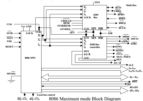
8288 Bus Controller – Bus Command and Control Signals:
8086 does not directly provide all the signals that are required to control the memory, I/O and interrupt interfaces.
Specially the WR, M/IO, DT/R, DEN, ALE and INTA, signals are no longer produced by the 8086. Instead it outputs three status signals S0, S1, S2 prior to the initiation of each bus cycle. This 3- bit bus status code identifies which type of bus cycle is to follow.
S2S1S0 are input to the external bus controller device, the bus controller generates the appropriately timed command and control signals.
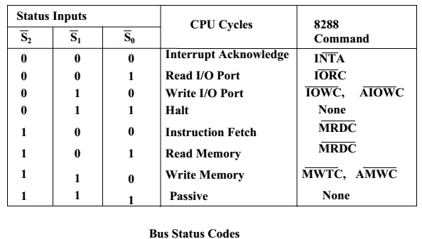
The 8288 produces one or two of these eight command signals for each bus cycles. For instance, when the 8086 outputs the code S2S1S0 equals 001, it indicates that an I/O read cycle is to be performed.
In the code 111 is output by the 8086, it is signaling that no bus activity is to take place.
The control outputs produced by the 8288 are DEN, DT/R and ALE. These 3 signals provide the same functions as those described for the minimum system mode. This set of bus commands and control signals is compatible with the Multibus and industry standard for interfacing microprocessor systems.
The output of 8289 are bus arbitration signals:
Bus busy (BUSY), common bus request (CBRQ), bus priority out (BPRO), bus priority in (BPRN), bus request (BREQ) and bus clock (BCLK).
They correspond to the bus exchange signals of the Multibus and are used to lock other processor off the system bus during the execution of an instruction by the 8086.
In this way the processor can be assured of uninterrupted access to common system resources such as global memory.
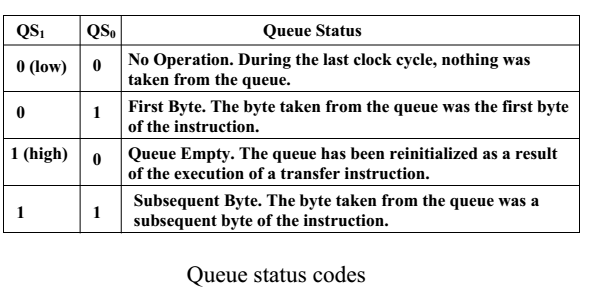
Queue Status Signals: Two new signals that are produced by the 8086 in the maximum-mode system are queue status outputs QS0 and QS1. Together they form a 2-bit queue status code, QS1QS0.
- Following table shows the four different queue status.
Local Bus Control Signal – Request / Grant Signals: In a maximum mode configuration, the minimum mode HOLD, HLDA interface is also changed. These two are replaced by request/grant lines RQ/ GT0 and RQ/ GT1, respectively. They provide a prioritized bus access mechanism for accessing the local bus.