Database Management System – Entity Relationship Model
Entity Relational Model (E-R Model)
The E-R model can be used to describe the data involved in a real world enterprise in terms of
objects and their relationships.
Uses:
- These models can be used in database design.
- It provides useful concepts that allow us to move from an informal description to precise description.
- This model was developed to facilitate database design by allowing the specification of overall logical structure
of a database. - It is extremely useful in mapping the meanings and interactions of real world enterprises onto a conceptual
schema. - These models can be used for the conceptual design of database applications.
ER model consists the following 3 steps.
a. Requirements Collection and Analysis:
This is the first step in designing any database application.
This is an informal process that involves discussions and studies and analyzing the expectations of the users & the intended uses of the database.
Under this, we have to understand the following.
- What data is to be stored n a database?
- What applications must be built?
- What operations can be used?
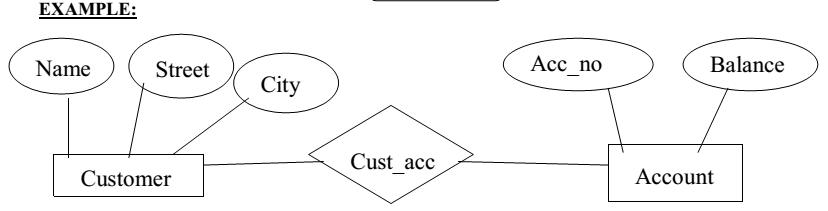
Example:
For customer database, data is cust-name, cust-city, and cust-no.
b. Conceptual database design:
The information gathered in the requirements analysis step is used to develop a higher-level description of the data. The goal of conceptual database design is a complete understanding of the database structure, meaning (semantics), inter-relationships and constraints.
Characteristics of this phase are as below.
- Expressiveness:
The data model should be expressive to distinguish different types of data, relationships and
constraints. - Simplicity and Understandability:
The model should be simple to understand the concepts. - Minimality:
The model should have small number of basic concepts. - Diagrammatic Representation:
The model should have a diagrammatic notation for displaying the conceptual schema. - Formality:
A conceptual schema expressed in the data model must represent a formal specification of the data.
Example:
Cust_name : string;
Cust_no : integer;
Cust_city : string;
c. Logical Database Design:
Under this, we must choose a DBMS to implement our database design and convert the conceptual database design into a database schema.
The physical database design can have the following options.
1.Response Time:
This is the elapsed time between submitting a database transaction for execution and receiving a
response.
2.Space Utilization:
This is the amount of storage space used by the database files and their access path structures on
disk including indexes and other access paths
3.Transaction Throughput:
This is the average number of transactions that can be processed per minute
5. Security Design:
In this step, we must identify different user groups and different roles played by various users.
For each role, and user group, we must identify the parts of the database that they must be able to access,
which are as below.
ENTITIES
- It is a collection of objects.
- An entity is an object that is distinguishable from other objects by a set of attributes.
- This is the basic object of E-R Model, which is a ‘thing’ in the real world with an independent existence.
- An entity may be an ‘object’ with a physical existence.
- Entities can be represented by ‘Ellipses’.
Example:
i. Customer, account etc.
ATTRIBUTES
Characteristics of an entity are called as an attribute.
The properties of a particular entity are called as attributes of that specified entity.
Example:
Name, street_address, city — customer database.
Acc-no, balance — account database.
Types of Attributes:
These can be classified into following types.
- Simple Attributes.
- Composite Attributes.
- Single Valued Attributes.
- Mutivalued Attributes.
- Stored Attributes.
- Derived Attributes.
Explanation is as below.
1.Simple Attributes:
The attributes that are not divisible are called as ‘simple or atomic attributes’.
Example:
cust_name, acc_no etc..
2.Composite Attributes:
The attributes that can be divided into smaller subparts, which represent more basic attributes with independent meaning.These are useful to model situations in which a user sometimes refers to the composite attribute as unit but at other times refers specifically to its components.
Example:
Street_address can be divided into 3 simple attributes as Number, Street and Apartment_no.
Street_address
City State Zip
3.Single Valued Attribute:
The attributes having a single value for a particular entity are called as ‘Single Valued Attributes’.
Example:
‘Age’ is a single valued attribute of ‘Person’.
4.Muti Valued Attribute:
The attributes, which are having a set of values for the same entity, are called as ‘Multi Valued Attributes’.
Example:
A ‘College Degree’ attribute for a person.i.e, one person may not have a college degree, another
person may have one and a third person may have 2 or more degrees.
A multi-valued attribute may have lower and upper bounds on the number of values allowed for each
individual entity.
5.Derived Attributes:
An attribute which is derived from another attribute is called as a ‘derived attribute.
Example:
‘Age’ attribute is derived from another attribute ‘Date’.
6.Stored Attribute:
An attribute which is not derived from another attribute is called as a ‘stored attribute.
Example:
In the above example,’ Date’ is a stored attribute
ENTITY SETS
Entity Type:
A collection entities that have the same attributes is called as an ‘entity type’.
Each entity type is described by its name and attributes.
Entity Set:
Collection of all entities of a particular entity type in the database at any point of time is called as an entity set.The entity set is usually referred to using the same name as the entity type.
An entity type is represented in ER diagrams as a rectangular box enclosing the entity type name.
Example:
Collection of customers.
Relationships
It is an association among entities.
Relationship Sets
It is a collection of relationships.
Primary Key:
The attribute, which can be used to identify the specified information from the tables
Weak Entity:
A weak entity can be identified uniquely by considering some of its attributes in conjunction with the primary key of another entity
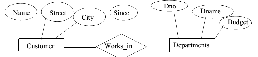
Descriptive Attributes:
A relationship can also have some attributes, which are called as ‘descriptive attributes’.
These are used to record information about the relationship.
Example:
James of ‘Employees’ entity set works in a department since 1991.
Instance:
An instance of a relationship set is a set of relationships.
It is a snapshot of the relationship at some instant of time
Ternary Relationship:
A relationship set, which is having 3 entity sets, is called as a ternary relationship.
Additional Features of the E-R Model
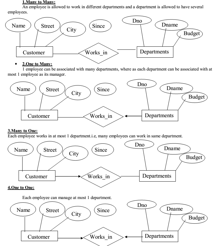
1.Key Constraints:
These can be classified into 4 types as below
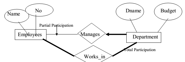
2.Participation Constraints:
The participation constraint specifies whether the existence of an entity depends on its being related to another entity via the relationship type.
A department has at most one manager. This requirement is an example of participation constraints.
There are 2 types of participation constraints, which are as below.
1.Total.
2.Partial.
Explanation is as below.
1.Total:
An entity set dependent on a relationship set and having one to many relationships is said to be ‘total’.
The participation of the entity set ‘departments’ in the relationship set ‘manages’ is said to be total.
2.Partial:
A participation that is not total is said to be partial.
Example:
Participation of the entity set ‘employees’ in ‘manages’ is partial, since not every employee gets to
manage a department.
In E-R diagram, the total participation is displayed as a ‘double line’ connecting the participating entity type to the relationship, where as partial participation is represented by a single line.
If the participation of an entity set in a relationship set is total, then a thick line connects the two.
The presence of an arrow indicates a key constraint.
3.Weak Entity Set:
Weak Entity Type:
Entity types that do not have key attributes of their own are called as weak entity types.
A weak entity type always has a ‘total participation constraint’.
A weak entity set can be identified uniquely only by considering some of its attributes in conjunction with
the primary key of another entity (Identifying owner).
For any weak entity set, following restrictions must hold.
- The owner entity set and the weak entity set must participate in a
One-to-many relationship set, which is called as the ‘Identifying
Relationship Set’ of the weak entity set. - The weak entity set must have total participation in the identifying relationship set.
Example:
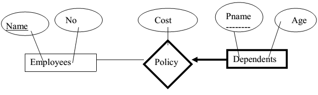
‘Dependents’ is an example of a weak entity set.
Partial key of the weak entity set:
The set of attributes of a weak entity set that uniquely identify a weak entity for a given owner entity is
called as ‘partial key of the weak entity set’.
Example:
‘Pname’ is a partial key for dependents.
The dependent weak entity set and its relationship to employees is shown in the following diagram.
Linking them with a dark line indicates the total participation of dependents in policy.
To understand the fact that dependents is a weak entity and policy is its identifying relationship, we draw
both with dark lines.
To indicate that ‘pname’ is a partial key for dependents, we underline it using a broken line.
4.Aggregation:
Aggregation is an abstraction for building composite objects from their component objects.
Aggregation is used to represent a relationship between a whole object and its component parts.
Aggregation allows us to indicate that a relationship set (identified through a dashed box) participates in
another relationship set.
This is illustrated with a dashed box around sponsors.
If we need to express a relationship among relationships, then we should use aggregation.
Aggregation versus Ternary Relationship:
We can use either aggregation or ternary relationship for 3 or more entity sets.
The choice is mainly determined by
a. The existence of a relationship that relates a relationship set to an
entity set or second relationship set.
b. The choice may also guided by certain integrity constraints that we
want to express.
1.A project can be sponsored by any number of departments.
2.A department can sponsor 1 or more projects.
3.1 or more employees monitor each sponsorship.
(Many to Many Relationship)
Consider the constraint that each relationship be monitored by at most 1 employee.
We cannot express this constraint in terms of the ternary relationship in the following diagram. In that
we are using a ternary relationship instead of aggregation.
Aggregation groups a part of an E-Are diagram into a single entity set allowing us to treat the aggregate
entity set as a single unit without concern for the details of it’s internal structure.
Thus, the presence of such a constraint serves as another reason for using aggregation rather than a
ternary relationship set.
Conceptual Database Design With The ER Model
The information gathered in the requirements analysis step is used to develop a higher-level description of the data. The goal of conceptual database design is a complete understanding of the database structure, meaning (semantics), inter-relationships and constraints.
Characteristics of this phase are as below.
1.Expressiveness:
The data model should be expressive to distinguish different
types of data, relationships and constraints.
2.Simplicity and Understandability:
The model should be simple to understand the concepts.
3.Minimality:
The model should have small number of basic concepts.
4.Diagrammatic Representation:
The model should have a diagrammatic notation for
displaying the conceptual schema.
5.Formality:
A conceptual schema expressed in the data model must
represent a formal specification of the data.
Example:
Cust_name: string;
Cust_no: integer;
Cust_city: string;
a. Entity Versus Relationships:
Suppose that each department manager is given a ‘Dbudget’ as shown in the figure.
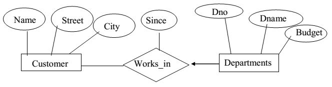
There is at most 1 employee managing a department, but a given employee could manage several
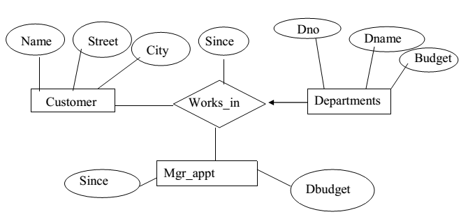
departments (1 to many relationships).We can store starting date and ‘Dbudget’ for each manager-department pair.This approach is natural, if we assume that a manager receives a single ‘Dbudget’ for each department that he manages. But if the ‘Dbudget’ is the sum of all departments, then ‘manages’ relationship that involves each employee will have the same value (total value).
So this leads to redundancy. This can be solved by the appointment of the employee as a manager of a group of departments. We can model ‘mgr_appt’ as an entity set for manager appointment, use a ternary relationship and we can have at most 1 manager for each department due to 1 to many relationship.
Conceptual Database Design For Large Enterprises
The process of conceptual database design consists describing small fragments of the application in terms of E-R diagrams.
For a large Enterprise, the design may require,
1. More than 1 designer.
2. Span data and application by a number of user groups.
Using a high level semantic data model such as ER diagrams for conceptual design offers the additional
advantages that,1.The high level design can be diagrammatically represented.2.Many people, who provide the input to the design process, easily understand it.An alternative approach is to develop separate conceptual sachems for different user groups and then integrate all those.
To integrate, we must establish correspondences between entities, relationships and attributes, so that this process is somewhat difficult.The relations of degree 1 are called as ‘Unary Relations’.The relations of degree 2 are called as ‘Binary Relations’.The relations of degree 3 are called as ‘Ternary Relations’.
The relations of degree n are called as ‘nary Relations’.
For Offline Study you can Download Pdf file from below link
Download Database Management System Entity Relationship Model PDF File