Microprocessor – Typical Organisation Of A Microcomputer System
Microcomputer Organization:
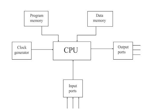
The basic components of a microcomputer are:
1) CPU
2) Program memory
3) Data memory
4) Output ports
5) Input ports
6) Clock generator.
These components are shown in figure below:
Central Processing Unit:
The CPU consists of ALU (Arithmetic and Logic Unit), Register unit and control unit. The CPU retrieves stored instructions and data word from memory; it also deposits processed data in memory.
a) ALU (Arithmetic and Logic Unit)
This section performs computing functions on data. These functions are arithmetic operations such as additions subtraction and logical operation such as AND, OR rotate etc. Result are stored either in registers or in memory or sent to output devices.
b) Register Unit:
It contains various register. The registers are used primarily to store data temporarily during the execution of a program. Some of the registers are accessible to the uses through instructions.
c) Control Unit:
It provides necessary timing & control signals necessary to all the operations in the microcomputer. It controls the flow of data between the p and peripherals (input, output & memory). The control unit gets a clock which determines the speed of the p.
The CPU has three basic functions
1) It fetches an instructions word stored in memory.
2) It determines what the instruction is telling it to do.(decodes the instruction)
3) It executes the instruction.
Executing the instruction may include same of the following major tasks.
1. Transfer of data from reg. to reg. in the CPU itself.
2. Transfer of data between a CPU reg. & specified memory location.
3. Performing arithmetic and logical operations on data from a specific memory location or a designated CPU register.
4. Directing the CPU to change a sequence of fetching instruction, if processing the data created a specific condition.
5. Performing housekeeping function within the CPU itself in order to establish desired condition at certain registers
4) It looks for control signal such as interrupts and provides appropriate responses.
5) It provides states, control, and timing signals that the memory and input/output section can use.
Program Memory:
The basic task of a microcomputer system into ensure that its CPU executes the desired instruction sequence is the program properly. The instruction sequence is stared in the program memory on initialization- usually a power up and manual reset the processor starts by executing the instruction in a predetermined location in
program memory. The first instruction of the program should therefore be in this location in typical µp basic system, the program to be executed is fixed one which does not change. Therefore µp program are store on ROM, or PROM, EPROM, EEPROM. In the trainer kit, ROM contains only the monitor program. The user program is not stored in ROM because it needs not to be stored permanently.
Data Memory:
A microcomputer manipulates data according to the algorithm given by the instruction in the program in the program memory. These instruction may require intermediate results to be stored, the
functional block in µc have same internal reg. which can also be used if available for such storage external data memory is needed if the storage requirements is more. Apart from intermediate storage, the data memory may also be used to provide data needed by the program, to store some of the results of the program. Data memory is used for all storage purposes other than storage of program. Therefore, they must have head write
capability RWM or RAM.
It stores both the instructions to be executed (i.e. program) and the data involved. It usually contains ROM (Read memory). The ROM can only read and cannot be written into and is non volatile that is, it retains its contents when the power is turned off. A ROM is typically used to store instructions and data that do not change. For example,it stores the monitor program if a microcomputer.
One can either read from or write into a RWM. The RWM is volatile, that is it does not retain its contents when the power is turned off. It is used to store user programmes & data which are temporary might change during the course of executing a program. Both ROM & RWM are RAM (Random access memory). RWM is respectively. During a memory read operation, the content of the addressed location is not destroyed. During a unit operation, the original content of the addressed location is destroyed.
Both ROM & RWM are arranged into words, each of which has a unique address. The address of a word is memory location and it is placed in parentheses. Therefore, X is an address and (X) is the content of that address X.
The address decodes taken an address and from the control unit and select the proper memory location and obtaining its content takes a certain amount of time, this times is the access time of the memory. The access time affects the speed of the computer, pins, and the computer must obtain the instruction and data from the memory. Computer memory as usually RAM so that all memory location have the same access time. The computer must wait shiner of unit’s memory, typical memory access time range from several uses. Memory sections often subdivided into units called pages.
The entire memory section may involve million of cords, when a page contains between 256 & 4k warts. The computer may access a memory location by first decreasing a particular page and then accessing a location on that page. The advantage of paging is that the computer can reach several locations on the same page with just the address in the page. The process is like describing street address by first specifying aspect and them listing the have numbers.
The control section transfers data to or from memory as follows.
1. The control section reads an address to the memory.
2. The control section sends a read and write signal to the memory to indicate, the direction of the transform.
3. The control section waits until transfer has been completed .this delay precedes the actual data’s transfer in the input case and follows it in the output case.
Input/Output Ports:
The input & output ports provide the microcomputer the capability to communicate with the outside world. The input ports allow data to pass from the outside world to the µc data which will be used in the data manipulation being done by the microcomputer to send data to output devices The user can enter instruction (i.e. program) and data in memory through input devices such as keyboard, or simple switches, CRT, disk devices, tape or card readers. Computers are also used to measure and control physical quantities like temperature, pressure, speed etc.
For these purposes, transducers are used to convent physical quantise into proportional electrical signals A/D computers are used to convert electrical signals into digital signals which are sent to the compute.
The computer sends the results of the computation to the output devices e.g. LED, CRT, D/A converters, printers etc.. These I/O devices allow the computer to communicate with the outside world I/O devices are called peripherals.
Clock Generator:
Operations inside the p as well as in other parts of the c, are usually synchronous by nature. The clock generator generates the appropriate clock periods during which instruction executions are carried out by the microprocessor. This condition ensures that events in different path of the systems can proceed in a systematic fashion.
Some of the microprocessors have an internal clock generator circuit to generate a clock signal. These microprocessors require an external crystal or RC network to be connected at the appropriate pins for deciding the operating frequency (e.g. 8085). Some microprocessors require an external clock generator (e.g. 8086).These microprocessors also provides an output clock signal which can be used by other devices in the microcomputer system for their can timing and synchronizing.