Microprocessor – Concept Of Interrupt
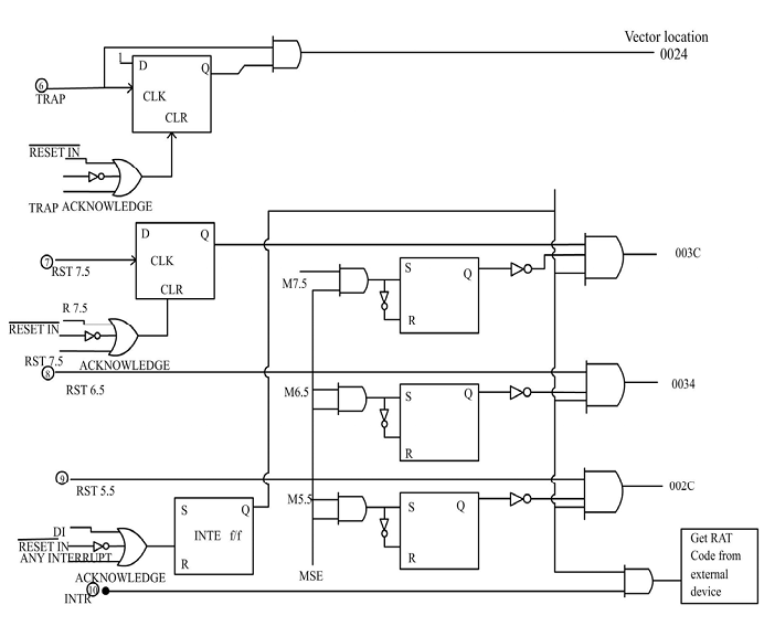
8085 interrupt structure
There are five interrupt input TRAP,RST 75,SRT 65,RST 55 and IWTR. TRAP is a nonmaskable interrupt, that is, it cannot be disabled by an instruction RST75,65,55 and INTR are maskable interrupt i.e. they can be enabled or disabled by software. The 8085 A interrupt structure is shown in fig.
INTE F/F :
When the power is ON for the first time, RESET IN (RESET IN BAR) signal goes Low.if resets the 8085.2f also resets the INTE F/F.so that the entire interrupt structure is disabled. The INTE F/F can be SET or RESET using instructions. When INTE F/F is reset, except for TRAR no other interrupt signal can interrupt the Microprocessor.
TRAP:
TRAP is a nonmaskable vectored interrupt, Most Microprocessor interrupt input are level sensitive however, some are edge sensitive and others are both edge and level sensitive, the TRAP input is both edge sensitive and level sensitive interrupt The positive edge of the TRAP signal will set the D flip flop .because of the AND gate, however the final TRAP also depends on a sustained high level TRAP input. This is why the TRAP is both edge and level sensitive this also avoids false triggering caused by noise and transients Since the TRAP input has the highest priority it is used for catastrophic events such as power failure, partly errors, and other events that require immediate attention. In the case of brief power failure it may be possible to save critical data with parity errors, the data may be resample or corrected before going on.
Whenever TRAP comes, Microprocessor completes the current instruction, pushes the program counter in the slack and branches to fixed location 0054 H. once the 8085A Microprocessor recognize a TRAP interrupts, it will send a high TRAP ACKNWNLEDGE bit to the TRAP F/F ,thus clears then F/F so that even of TRAP is high it is not recognize only if it goes low, then high and remains high. The TRAP F/F is also cleared when Microprocessor is being reset during which RESET IN BAR goes low and clears the F/F.
RST7.5, 6.5, &5.5:
These are maskable vectored interrupts. These interrupts can be enabled or disabled through software. RST 7.5 has the highest priority among these & RST 55 has the lowest priority.RST 75 control signal input is rising edge sensitive interrupt whenever LOW to HIGH instruction occurs ,The output of this F/F is labelled I 7.5.whenever the other input are high the Microprocessor recognize this interrupt this request is remembered until (1).the 8085 A responds to the interrupt (when interrupt is acknowledged, it sends a high RS77.5 ACKNOWLEDGE bit to the clear input this clears it for future interrupts of D F/F. (2).or until the request is RESET by SIM instruction (R 7.5 bit is made high through SIM instruction and the F/F can be cleared) (3).or until the Microprocessor is being reset ie RESER IN BAR signal becomes LOW whenever RST 7.5 is recognized, control is transferred to 003cH RST 6.5 & 5.5 are also vectored masked interrupts and are HIGH level sensitive interrupt control signal input. These are directly connected to AND gate the signal at these inputs must be maintained until the interrupt is acknowledged. Whenever RST 6.5 is recognized, the control is transferred to 0034 H & whenever RST5.5 is recognized, the control is transferred to 002CH. The signals I7.5,6.5 & 5.5 are called pending interrupts .the signal IE (bottom F/F) is called interrupt enable flag, it must be high to active The AND gates, Also notice the M7.5,M6.5 & M5.5 signals, they must be low to enable the AND gates. e.g. to activate RST7.5 interrupt, I7.5 must be high, M7.5 must be low and IE must be high. The interrupt enable F/F can be set or reset through software then F/F can be set using EI instruction. EI stands for enable interrupt whenever EI is executed, it produces a high EI bit and sets the INTE F/F and produces=a high IE output.
This f/F can be reset in three ways.
1). When the power is on for the first time or signal goes low, it resets the INTE F/F so that that entire interrupt structure is disabled. When INTE F/F is reset except for TRAP no other interrupt can interrupt the Microprocessor .
2).the INTE F/F can be reset using DI instruction. DI stands for disable interrupt when executed it produces a high DI bit & clear the INTE F/F
3).when the 8085 recognize an interrupt, it produces a high ANY INTERRUPT ACKNOWLEDGE bit .this disables the interrupts
Because the interrupts are automatically disabled by the ANY INTERRUPT ACKNOWLEDGE bit programmer usually includes an EI as the next to last instruction in the service subroutine. For instance the last two instructions typically are Subroutine:
EI
RET
This subroutine cannot be interrupted (except by a TRAP) after the EI is executed, the processing returns to the main program with the interrupt system enabled.
M7.5, M 6.5 & M5.5 are mask F/F s these flip-flop are used individually to mask the interrupts. where these F/Fs are set, then the corresponding interrupt is masked (Q=1, =0) and the interrupt control signal cannot interrupt the p .these mask F/Fs are SET to during power ON by RESET IN BAR control signal going LOW these MASK F/Fs can be individually and selectively clear to ‘o’ through SIM instruction. Mask set enable F/F is also set this (MSE) can also be SET to 1 simultaneously using SIM instruction
INTR:
INTR is a maskable interrupt. A HIGH level on this pin interrupt the Microprocessor .the interrupt signal input INTR is not affected by SIM instruction only INTE F/F must be SET to 1 before this interrupt comes