Digital Electronics – S-R (Set-Reset) Flip-flop
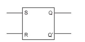
An S-R flip-flop has two inputs named Set (S) and Reset (R), and two outputs Q and Q’. The outputs are complement of each other, i.e., if one of the outputs is 0 then the other should be 1. This can be implemented using NAND or NOR gates. The block diagram of an S-R flip-flop is shown in Figure below:-
S-R Flip-flop Based on NOR Gates
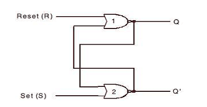
An S-R flip-flop can be constructed with NOR gates at ease by connecting the NOR gates back to back as shown in Figure below. The cross-coupled connections from the output of gate 1 to the input of gate 2 constitute a feedback path. This circuit is not clocked and is classified as an asynchronous sequential circuit.
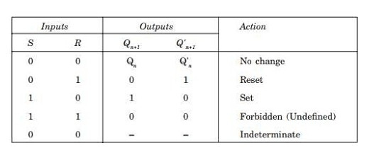
The truth table for the S-R flip-flop based on a NOR gate is shown in the table below
To analyze the circuit of S-R Flip-flop Based on NOR Gates, we have to consider the fact that the output of a NOR gate is 0 if any of the inputs are 1, irrespective of the other input. The output is 1 only if all of the inputs are 0.
The outputs for all the possible conditions as shown in the above table are described as follows.
Case 1. For S = 0 and R = 0, the flip-flop remains in its present state (Qn). It means that the next state of the flip-flop does not change, i.e., Qn+1 = 0 if Qn = 0 and vice versa. First let us assume that Qn= 1 and Q’n= 0.Thus the inputs of NOR gate 2 are 1 and 0, and therefore its output Q’n+1 = 0. This output Q’n+1 = 0 is fed back as the input of NOR gate1, thereby producing a 1 at the output, as both of the inputs of NOR gate 1 are 0 and 0; so Qn+1 = 1 as originally assumed. Now let us assume the opposite case, i.e., Qn = 0 and Q’n = 1.
Thus the inputs of NOR gate 1 are 1 and 0, and therefore its output Q’n+1 = 0. This output Qn+1 = 0 =0 is fed back as the input of NOR gate 2, thereby producing a 1 at the output, as both of the inputs of NOR gate 2 are 0 and 0; so Q’n+1 = 1 as originally assumed. Thus we find that the condition S = 0 and R = 0 do not affect the outputs of the flip-flop, which means this is the memory condition of the S-R flip-flop.
Case 2. The second input condition is S = 0 and R = 1. The 1 at R input forces the output of NOR gate 1 to be 0 (i.e., Qn+1 = 0). Hence both the inputs of NOR gate 2 are 0 and 0 and so its output Q’n+1 = 1. Thus the condition S = 0 and R = 1 will always reset the flip-flop to 0. Now if the R returns to 0 with S = 0, the flip-flop will remain in the same state.
Case 3. The third input condition is S = 1 and R = 0. The 1 at S input forces the output of NOR gate 2 to be 0 (i.e., Q’n+1 = 0). Hence both the inputs of NOR gate 1 are 0 and 0 and so its output Qn+1 = 1. Thus the condition S = 1 and R = 0 will always set the flip-flop to 1. Now if the S returns to 0 with R = 0, the flip-flop will remain in the same state.
Case 4. The fourth input condition is S = 1 and R = 1. The 1 at R input and 1 at S input forces the output of both NOR gate 1 and NOR gate 2 to be 0. Hence both the outputs of NOR gate 1 and NOR gate 2 are 0 and 0; i.e. Qn+1 = 0 and Q’n+1 = 0. Hence this condition S = 1 and R = 1 violates the fact that the outputs of a flip-flop will always be the complement of each other. Since the condition violates the basic definition of flip-flop, it is called the undefined condition.
Generally this condition must be avoided by making sure that 1s are not applied simultaneously to both f the inputs.
Case 5. If case 4 arises at all, then S and R both return to 0 and 0 simultaneously, and then any one of the NOR gates acts faster than the other and assumes the state. For example, if NOR gate 1 is faster than NOR gate 2, then Qn+1 will become 1 and this will make Q’n+1 = 0. Similarly, if NOR gate 2 is faster than NOR gate 1, then Q’n+1 will become 1 and this will make Qn+1 = 0.
Hence, this condition is determined by the flip-flop itself . Since this condition cannot be controlled and predicted it is called the indeterminate condition.