Digital Electronics – Digital Logic Short Study Notes
This section Contains digital electronics study notes, we have compiled this notes for the readers to know what they learned or what they will learn in the subject of digital electronics . this will help them for Quick revision.
Number system: the system used to count discrete units is called number system.
Decimal system: the number system that contains 10 distinguished symbols that is 0-9 or digits is called decimal system. As per the number of symbols its base or radix is 10.
Binary number system: the number system that contains only two distinguished symbols that is 0 and 1 is called binary number system. its base or radix is 2.
Hexadecimal number system: the number system that contains 16 distinguished symbols that is 0-9 and A,B,C,D,E,F is called hexadecimal number system. It’s base or radix is 16.
Conversion from binary number to decimal number is done as given below
(11011)2 = 1 + 1 + 0 + 1 + 1 = 16 + 8 + 0 + 2 + 1 =2710
Conversion from hexadecimal to decimal number is done as given below
(A6B) 16 = A162 + 6 161 + B 160
= 10 256 + 6 + 11 = 2460 + 96 + 11 = 266710
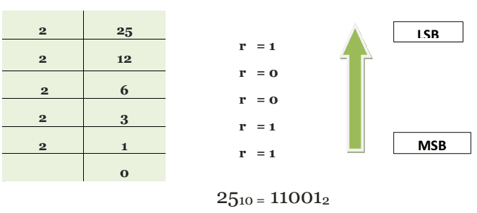
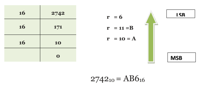
Conversion from decimal number to hexadecimal number is done as shown below
Binary coded decimal system: it is another commonly used number system which is used in the field of digital electronics. in this case which digit of the decimal number is represented by 4 bit binary number example:
35910= 0011 0101 1001 (BCD)
Where 310 = 00112 ; 510 = 01012 ; 910 =10012 ;
The ASCII code: ASCII means American standard code for information interchange. is an alphanumeric code every numerals, letters and symbols of the board or printer is equipped with an ASCII code.
Logic Gates: an electronic circuit which may have one, 2 or more input signals but only one output signal is called logic Gate.
truth table: a tabular listing of all possible combination of inputs, for a logic Gate and the resultant output for each combination encoder truth table.
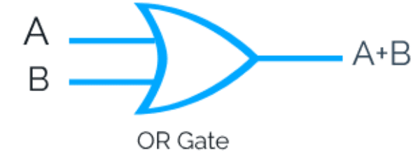
OR Gate: it is logic Gate which has Low output when no input is high but the output is high when any or all inputs are high.
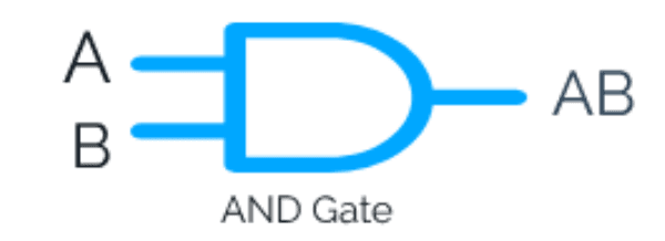
AND Gate: it is logic Gate which is high output only when all the inputs are high what output is low when any are all the inputs are low.
The Inverter or NOT GATE: what is logic Gate which is higher output when the input is low and output is low when the input is high, this Gate has only one input.

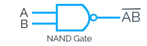
NAND Gate: it is logic Gate which is low output when all the inputs are high but output is high when any or all inputs are low.
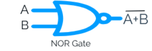
NOR Gate: it is the logic Gate which has high output window input is high but the output is low when any or all inputs are high.
Exclusive OR -EXOR Gate: It is a logic Gate which is higher output when both the inputs are identical that is either both are high for both are low.

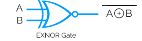
Exclusive NOR -XNOR Gate: it is a logic Gate which has high output when both the inputs are identical that is either both are high or both are low.
Boolean Algebra: the mathematical operation by which various input variables, output variables and Boolean operations are interrelated.
Boolean equations a simplified by applying various theorems
De Morgan’s theorem:
First theorem: it states that the component of a sum equals the product of the components.That is ![]()
Second theorem: it states that complement of a product equals the sum of the components that is ![]()
Karnaugh map: it is a method of simplifying Boolean functions or logic circuits a systematic mathematical way.
Pair: Karnaugh map that contains adjacent 1s horizontally or vertically is called pair.
Quad: when four adjacent 1s a grouped horizontally, vertically or in a square, the group so formed is called a quad.
Octet: when 8 adjacent 1s are grouped horizontally or vertically, the group so formed is called an octet.
Redundant groups: group whose 1s are all overlapped by other groups is called redundant group.
NAND or NOR Universal gates: these are called Universal Gates because this Gates can be used in place of all other Gates that is NOT, AND, OR, XOR etc.
Binary addition: following rules are employed by adding binary numbers
0 + 0 equal to zero
0 + 1 equal to 1
1 + 0 equal to 1
1 + 1 equal to 10
1 + 1 + 1 equal to 11
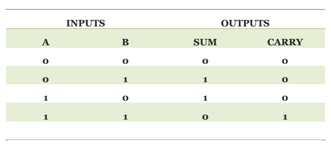
Half adder: logic circuit which is used to add two binary bits is called a half adder. The output of the half adder is sum and carry. The Boolean expression and truth table of these outputs are:
Sum= A ⊕B
Carry = AB
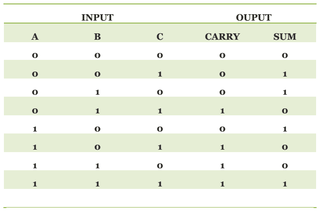
Full adder: a logic circuit which is used to add 3 binary bits is called a full adder. It has two outputs sum and carry. The Boolean expressions and truth table of these outputs are
Sum= A ⊕B ⊕C
Carry = AB + AC + BC
Complete binary adder: half adders and full adders are usually combined to add longer binary numbers.
Encoder: encoder is a device which converts the language of the people to the language of the machine.
Decoder: Decoder converts the machine language to the people language.
Flip flop: bistable multivibrator is also known as flip flop.
Rs flip flop: in Rs flip flop has two inputs namely reset and set accordingly it is known as Rs flip flop.
Clocked the Rs flip flop: to an Rs flip flop, when third input clock is added, the flip flop is known as clocked Rs flip flop.
D flip flop: in Rs flip flop which delays the Digital Signal by the duration of one clock cycle is called a D flip flop.
Edge triggered D flip flop: it is the most common type of D flip flop. it samples the bit or data at a unique instant.
JK flip flop: Universal flip flop, J and K are called control inputs because they determine what the flip flop does when a positive clock edge arrives.
Register: a group of memory elements that work together as a unit is called a resistor.
Buffer register: buffer register is the simplest kind of register. it is used only to store a digital word.
Shift register: shift register is an array of flip flops design to store and shift the data.
Counters: counter is a register capable of counting the number of clock pulses that have arrived at its clock input.
Ripple counter: when the output of one flip flop drives another, we call the counter as a ripple counter or an asynchronous counter.
For Offline Study you can Download pdf file from below link
![]() Digital Electronics Short Study notes PDF
Digital Electronics Short Study notes PDF